Magnet with electromagnetic coil/impedance/sensor element

a magnet and coil technology, applied in the field of magneto impedance sensor element miniaturization, high sensitivity, wide range of magneto impedance sensor element, can solve the problems of insufficient miniaturization of high-performance magnetic sensor element, and the size of mi element was necessarily large, so as to reduce the required power, and reduce the size of the element.

Inactive Publication Date: 2005-06-02
AICHI STEEL
View PDF1 Cites 8 Cited by
  • Summary
  • Abstract
  • Description
  • Claims
  • Application Information

AI Technical Summary

Benefits of technology

[0008] The purpose of this invention is to achieve smaller form and volume, lower power consumption, higher sensitivity, and wider range in an MI element.
[0018] In the magneto impedance sensor element with electromagnetic coil, comprised as described above in the first aspect of the invention, a smaller, thinner shape and lower power consumption is made possible. A groove has been extended in one direction on a terminal board. Inside this extended groove one part of a coil has been formed spirally, and joined to each tip of that coil the other part of the coil is placed across the top of the groove, so that together the two parts form a complete spiral. This complete electromagnetic coil forms a magnetic sensitive body, which is inserted into the extended groove on the above terminal board and surrounded with insulating resin. When either high frequency or pulse electrical current is applied to the magnetic sensitive body, voltage is output from the above electromagnetic coil in response to the intensity of the external magnetic field which is generated in the electromagnetic coil. Due to this construction, further miniaturization and a reduction in required power is realized.
[0021] In the magneto impedance sensor element with electromagnetic coil, comprised as described above in the fourth aspect of the invention, the electromagnetic coil mentioned in the third aspect of the invention has a line spacing separation per turn of not more than 100 micrometers. Due to this construction, a high density electromagnetic coil is realized, thereby also realizing higher sensitivity.

Problems solved by technology

However, inadequate miniaturization in high performance magnetic sensors was a problem.
However, because conventional MI elements were constructed with an electromagnetic coil wound external to the terminal board, the size of MI elements was necessarily large.

Method used


Image

  • Magnet with electromagnetic coil/impedance/sensor element
  • Magnet with electromagnetic coil/impedance/sensor element
  • Magnet with electromagnetic coil/impedance/sensor element

Examples


first embodiment

The First Embodiment

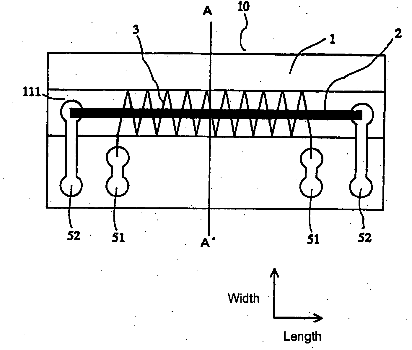
[0041] The first embodiment of the present invention (magneto impedance sensor element with electromagnetic coil) is as the MI element is shown in FIG. 1 and FIG. 2. Magnetic sensitive body 2 is provided on terminal board 1, and will detect magnetic fields. Between magnetic sensitive body 2 and electromagnetic coil 3, there is no separate circuit board on which the magnetic sensitive body 2 will be set. By setting up the electromagnetic coil 3 with only insulation surrounding the magnetic sensitive body 2, the electromagnetic coil 3 is arranged with a diameter less than 200 micrometers. The terminals of the magnetic sensitive body 2 and coil 3 are connected to electrodes 51 and 52 respectively on the terminal board 1. When either high frequency or pulse electrical current is applied to magnetic sensitive body 2, voltage is output in accordance with the intensity of the external magnetic field that is generated in the electromagnetic coil 3.

[0042] By setting up c...

second embodiment

The Second Embodiment

[0052] The second embodiment of the present invention is stated below.

[0053] Generally speaking, high sensitivity magnetic sensors have high sensitivity because the change in detection output per change in detection input is large, but because they immediately reach full scale up to magnetic field saturation, their detection range is narrow. One possible method to widen the range is to lessen the aspect ratio (proportion of wire length to wire diameter in the magnetic field detection element) and take advantage of a demagnetizing field.

[0054] However, the above-mentioned conventional magnetic sensor (MI, FG sensor), constructed as shown in FIG. 13, is limited in its miniaturization, and when miniaturized in order to have a high demagnetizing field, it suffers a severe deterioration of sensitivity.

[0055] Therefore, the second embodiment of the present invention is designed to provide a means to obtain an extremly small aspect ratio, which is the ratio of amorp...

example embodiment 1

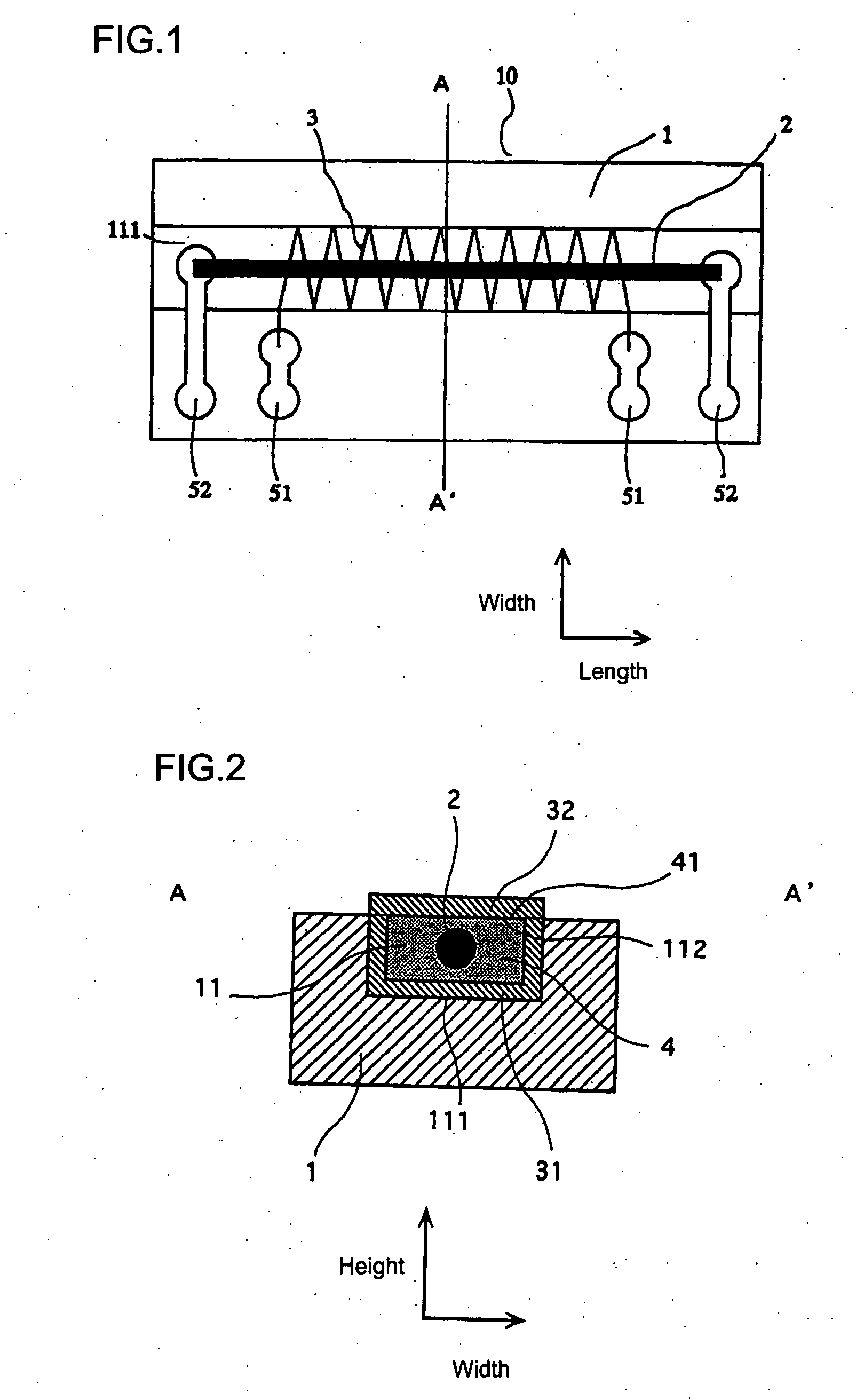
[0060] Example 1 of the magneto impedance sensor element with electromagnetic coil is illustrated in FIG. 1 and FIG.2.

[0061] The size of circuit board 1 is width 0.5 mm, height 0.5 mm, length 1.5 mm. The magnetic sensitive body is amorphous metal wire 2, using a CoFeSiB alloy of diameter 20 micrometers or 30 micrometers. Groove lion the circuit board is depth 50 micrometers, width 70 micrometers, and length 1.5 mm. Electromagnetic coil 3 has a two layer structure comprised of coil side 31, formed on groove surface 111, and remaining side coil 32 formed on groove exterior 112 (exterior 41 of resin 4).

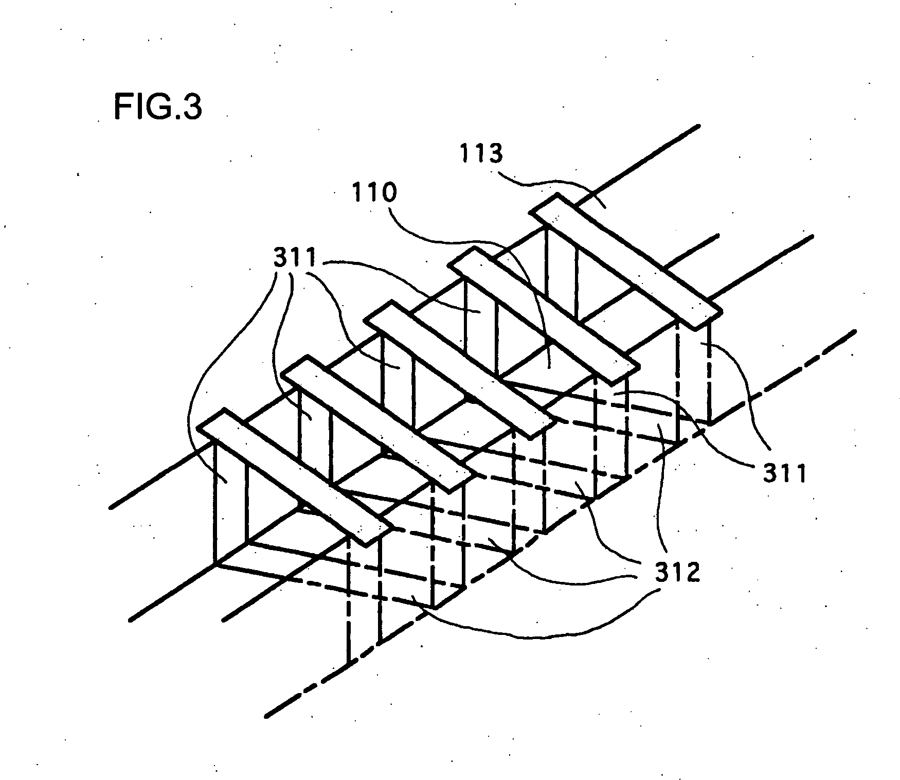
[0062] Coil side 31, formed on said groove surface 111, is comprised as shown in FIG. 3 through FIG. 5 and described below. Along the entire surface of groove surface 111 of groove 11, which is formed lengthwise on terminal board 1, and the adjoining part of said groove 11 on the surface of terminal board 1, a coil is formed of conductive thin metal film, which is deposited on that sur...


PUM


Abstract

A magneto impedance sensor element with electromagnetic coil comprised of: a terminal board (1) on which an extended groove (11) which extends in one direction has been formed; an electromagnetic coil(3), made with one part of the coil (31) formed in a spiral shape inside the extended groove (11) in the terminal board (1), and joined to each tip of that coil the other part of the coil (32) placed across the top of the groove; insulating material (4) placed in the extended groove (11) on the terminal board(1); and a magnetic sensitive body (2) inserted within the insulating material (4), to which either high frequency or pulse electic current is applied. When either high frequency or pulse electrical current is applied to the magnetic sensitive body, voltage is output from the above electromagnetic coil in response to the intensity of the external magnetic field which is generated in the electromagnetic coil.

Description

TECHNICAL FIELD OF THE INVENTION [0001] The present invention pertains to the miniaturization, high sensitivity, and wide range of a magneto impedance sensor element (hereinafter referred to as MI element) which is a magnetic sensor and incorporates an electromagnetic coil. The automotive industry is one concrete example of its possible application. BACKGROUND OF THE INVENTION [0002]FIG. 13, (Japanese Patent Laid-open No. 2000-81471, 2001-296127) shows the construction of a conventional MI element. [0003] In the central part of the MI element is a magnetic sensitive body made from amorphous metal wire. The magnetic sensitive body is set on a terminal board, around which an electromagnetic coil is wound. The conventional MI element uses an electromagnetic coil ranging in diameter from 1 to 5 mm, and the usual size of an MI element is width 3 mm, height 2 mm, length 4 mm. [0004] The above mentioned conventional MI element was able to achieve some degree of high sensitivity, miniaturiz...

Claims


Application Information

Patent Timeline
Patent Type & Authority Applications(United States)
IPC IPC(8): G01R33/02
CPCG01R33/02
Inventor HONKURA, YOSHINOBUYAMAMOTO, MICHIHARUMORI, MASAKIKOUTANI, YOSHIAKI
Owner AICHI STEEL
Why Eureka
Try Eureka