
Thermophotovoltaic power supply

a technology of photovoltaic power supply and photovoltaic generator, which is applied in the direction of photovoltaics, electrical equipment, and semiconductor devices, etc., can solve the problems of micro-power systems, short operating cycles between charges or replacements of typical portable mechanical devices, and limited miniaturization of these devices

Inactive Publication Date: 2005-06-09
NAT UNIV OF SINGAPORE
View PDF8 Cites 30 Cited by
  • Summary
  • Abstract
  • Description
  • Claims
  • Application Information

AI Technical Summary

Benefits of technology

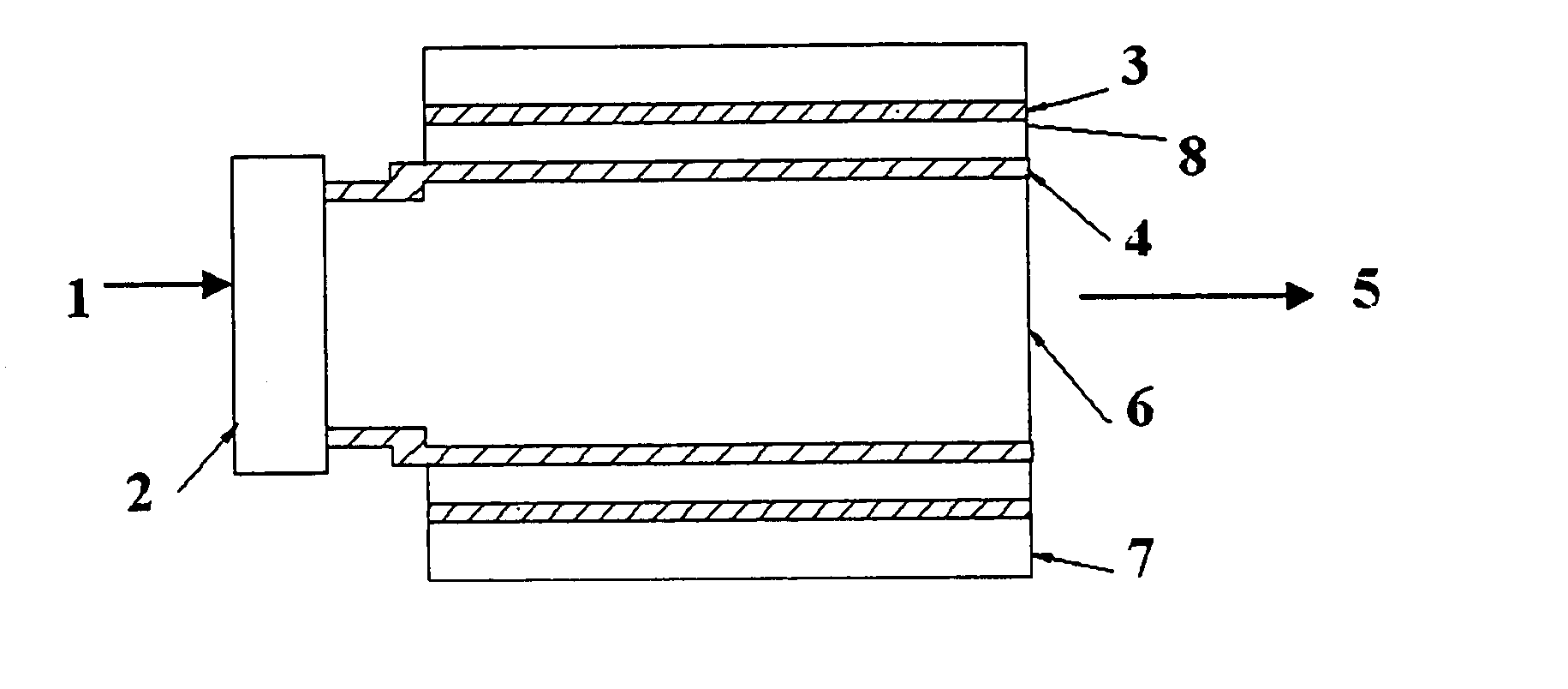
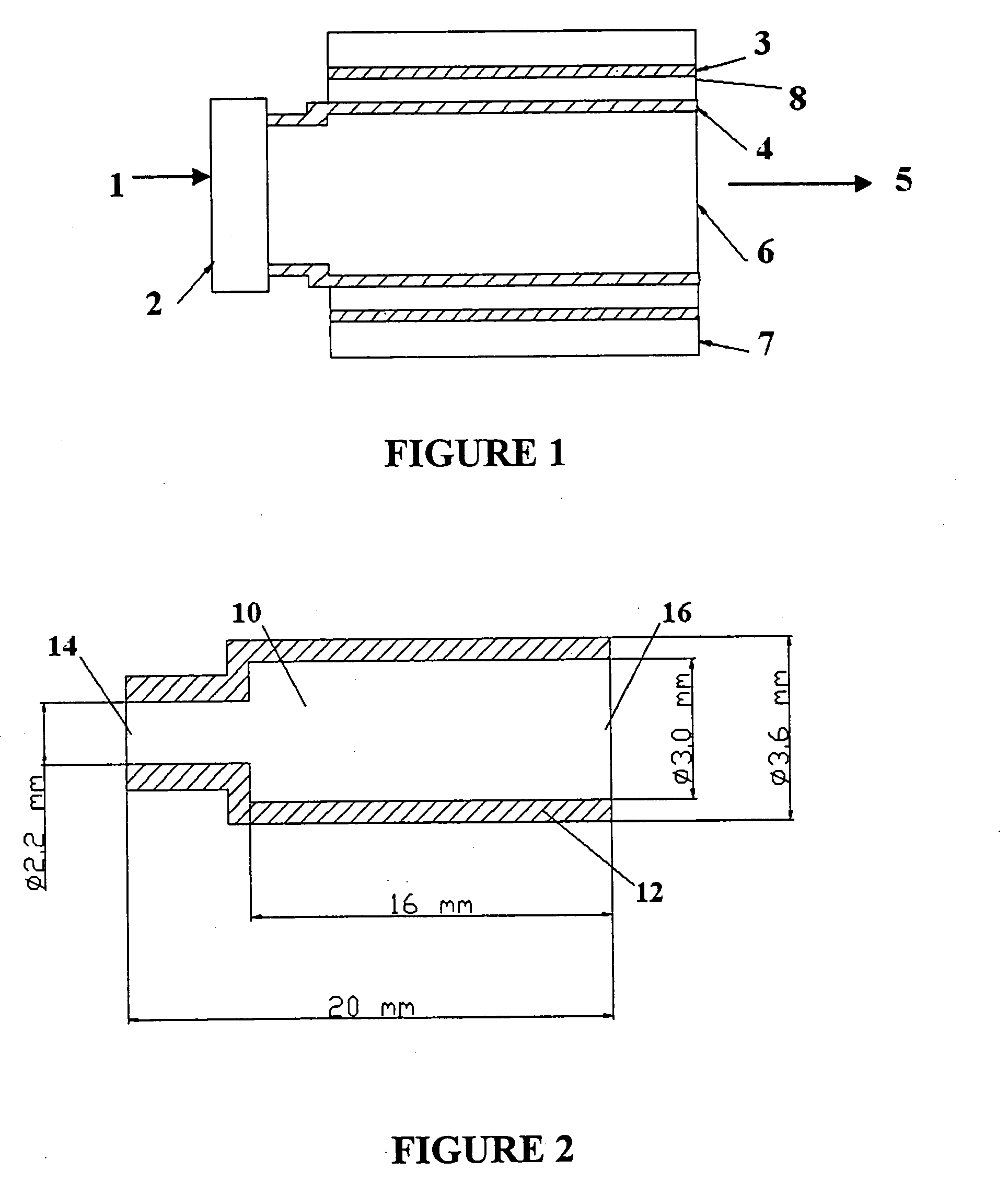
The present patent application describes a micro TPV generator that can generate electrical current from photons incident on a photovoltaic cell. The generator includes a combustion chamber with a uniform temperature distribution, an emitter in thermal connection to the chamber, and a photovoltaic cell in proximity to the emitter. The emitter can have a similar emission characteristic to the cell, and a filter can be used to pass photons above a certain threshold and reflect photons under it. The generator can be designed for hydrogen fuel or propane at different pressures. The invention also includes various constructions and applications of the micro TPV generator.

Problems solved by technology

However, the miniaturization of these devices is limited by the weight of the available power systems (batteries) that occupy significant fractions of both mass and volume of the entire devices.
Typical portable mechanical devices also suffer from short operating cycles between charges or replacement.
The above micro-power systems experience one major challenge, the high heat losses due to the high surface-to-volume ratio.

Method used


Image

  • Thermophotovoltaic power supply
  • Thermophotovoltaic power supply
  • Thermophotovoltaic power supply

Examples


Embodiment Construction

[0035] The present invention overcomes or at least ameliorates the shortcomings of high heat loss due to the high surface-to-volume ratio of a microcombustor. The micro-TPV system is a novel micro power generator which uses photovoltaic (PV) cells to convert heat radiation, for example from the combustion of fuels, into electricity. For micro-TPV application, the desired output is a high and uniform temperature along the wall of the microcombustor. Compared to conventional macro-TPV systems, the micro-TPV systems feature a much higher power density per unit volume due to the high surface-to-volume ratio.

[0036] For example, for a macro-TPV system with a cylindrical combustor of 50 cm in length and 20 cm in diameter, the surface and volume of the combustor are 3142 cm2 and 15708 cm3. Assuming the radiation power density is 10 W / cm2, the total radiation power from the combustor is 31420 W, corresponding to a volumetric power density 2 W / cm3. However, for a micro-TPV system with a cyli...


PUM


Abstract

A microthermophotovoltaic (micro-TPV) system is a novel micro power device. The system fully utilizes the high surface-to-volume ratio of a microcombustor, and is able to deliver and electrical power output of 0.5-10 W in a package of the order of centimeters. The system comprises mainly a combustor-emitter, a filter, a photovoltaic (PV) cell array, and cooling fins. The combustor-emitter functions to convert chemical energy into radiative heat energy. The filter is able to recycle a large part of the unusable energy that cannot be converted into electricity by the PV cell array. The PV cell array is used to convert radiative heat energy into electricity. The system has no moving parts. Its fabrication and assembly are relatively easy. As a result, it can be readily used as a power source of micro mechanical devices and portable devices, in which convenience and low cost reliability and ease of maintenance are the key factors of consideration.

Description

BACKGROUND OF THE INVENTION [0001] The present invention relates generally to thermophotovoltaic generators, and more particularly but not solely to micro generators. [0002] There is a rapidly growing trend in the miniaturization of mechanical and electro-mechanical engineering devices. All kinds of microdevices such as micro-pumps, micro-motors, micro-robots, micro-rovers and micro-airplanes are being developed. However, the miniaturization of these devices is limited by the weight of the available power systems (batteries) that occupy significant fractions of both mass and volume of the entire devices. Typical portable mechanical devices also suffer from short operating cycles between charges or replacement. The need to reduce system weight and increase operational lifetimes is behind the emergence of a new class of microelectromechanical system (MEMS) devices, micro power generators that are characterized by high power and energy density but small in size and weight, and are cost...

Claims


Application Information

Patent Timeline
Patent Type & Authority Applications(United States)
IPC IPC(8): H01L31/00H01L31/0216H01L31/04H01L31/068
CPCH01L31/02167H02S10/30Y02E10/544H01L31/0693Y02E10/547
Inventor CHOU, SIAW KIANGSHU, CHANGYANG, WEN MINGXUE, HONGLI, ZHI WANG
Owner NAT UNIV OF SINGAPORE
Learn More