
Residual frequency error estimation in an OFDM receiver

Active Publication Date: 2005-06-09
ADVANCED MICRO DEVICES INC
View PDF7 Cites 27 Cited by
  • Summary
  • Abstract
  • Description
  • Claims
  • Application Information

AI Technical Summary

Benefits of technology

[0011] There is a need for an arrangement that enables a direct conversion receiver to accurately estimate residual frequency error induced from noise components in a short preamble and a long preamble, and oscillator drift, to provide precise elimination of frequency errors between a direct conversion transmitter and the direct conversion receiver.

Problems solved by technology

Hence, implementation concerns typically involve cost, device size, and device complexity.
The resulting frequency error (fE=fT−fR) may cause substantial deterioration of the signal to noise ratio of left uncorrected.
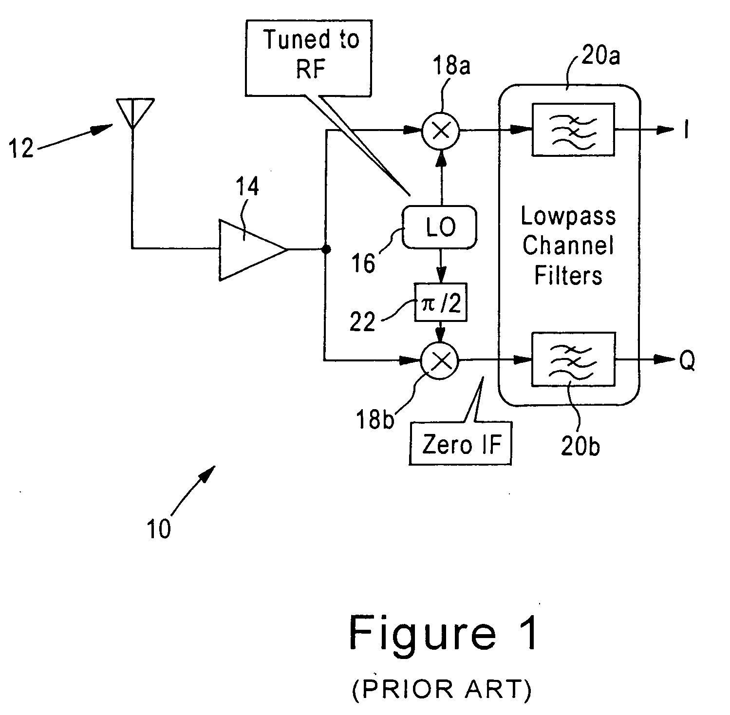
In actual implementation, however, the estimated frequency error (fEST) does not equal the actual frequency error (fE) because both the short preamble and long preamble contain noise components from transmission between the OFDM transmitter and the OFDM receiver 10.
Further, the short and long preamble output by the OFDM transmitter do not address frequency errors encountered due to oscillator drift, where the transmit frequency (fT) and the receive frequency (fR) independently vary over time.

Method used


Image

  • Residual frequency error estimation in an OFDM receiver
  • Residual frequency error estimation in an OFDM receiver
  • Residual frequency error estimation in an OFDM receiver

Examples


Embodiment Construction

[0021] The disclosed embodiment will be described with reference to an overview of an IEEE 802.11 OFDM transceiver, followed by a detailed description of the residual frequency error estimation according to an embodiment of the present invention.

Receiver Architecture Overview

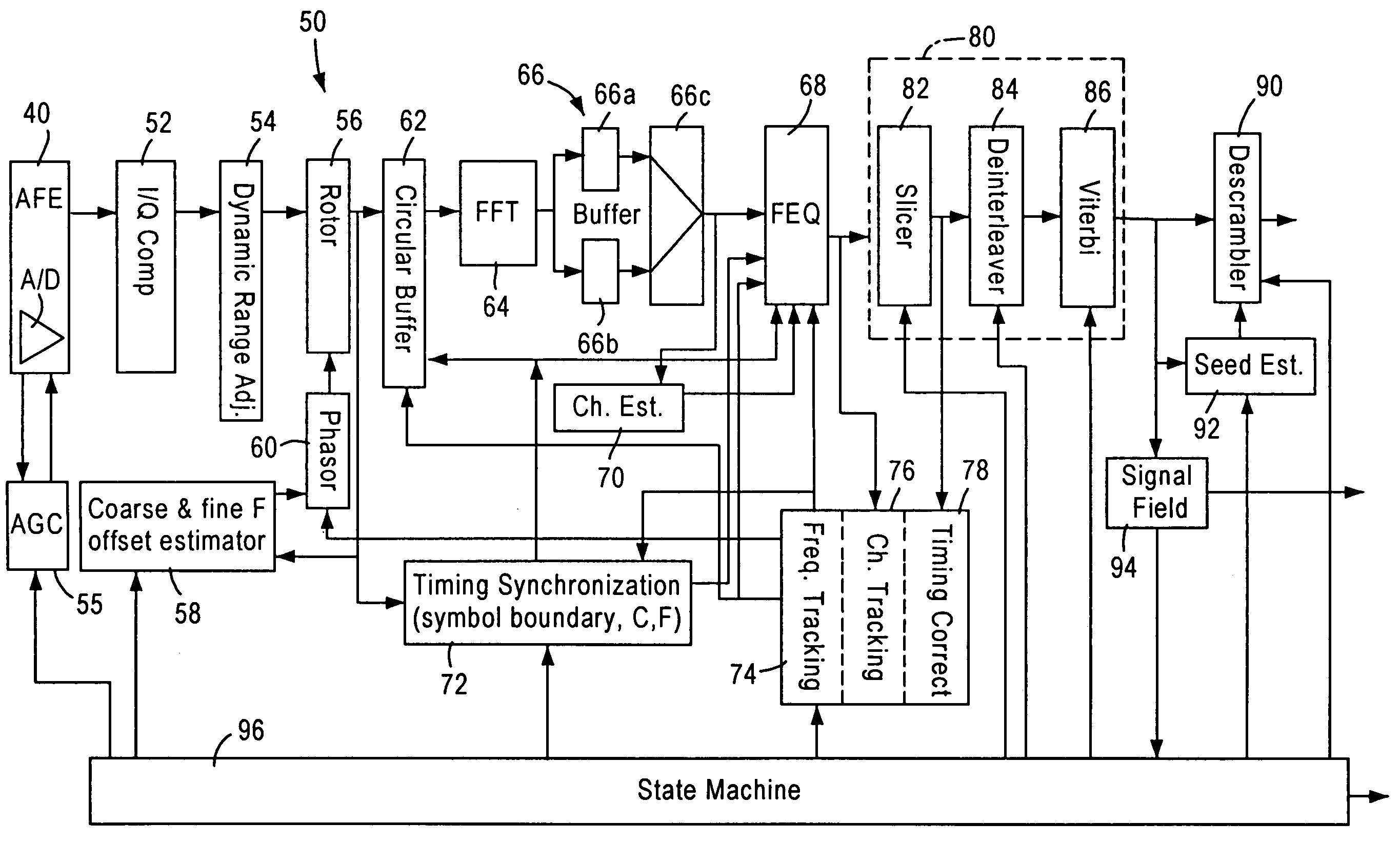
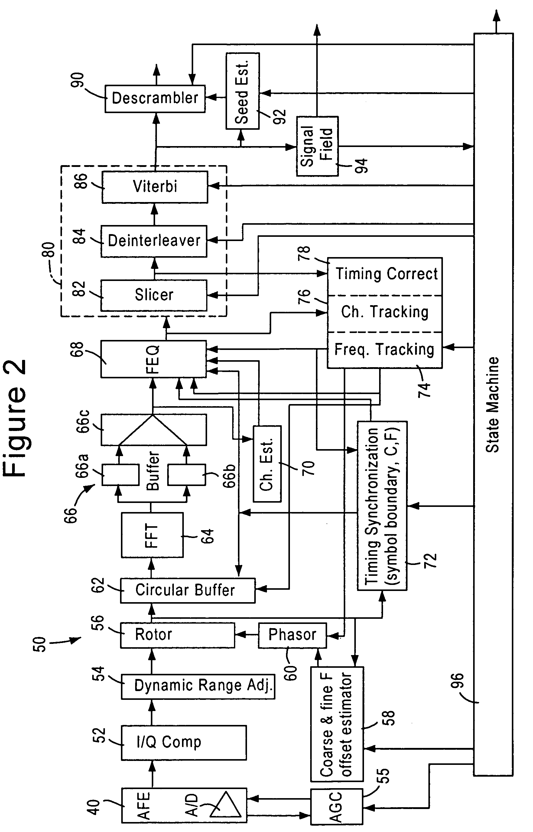
[0022]FIG. 2 is a diagram illustrating an architecture of a receiver module 50 of an IEEE 802.11 Orthogonal Frequency Division Multiplexing (OFDM) transceiver, according to an embodiment of the present invention. The receiver module 50, implemented as a digital circuit, includes an I / Q mismatch compensation module 52 that receives detected wireless signal samples (in digital form) from an R / F analog front end (AFE) amplifier 40 having an analog to digital (A / D) converter. The gain of the AFE amplifier 40 is controlled by an AGC module 55. The detected wireless signal samples include an I component and Q component: these I and Q components, which ideally should be orthogonal to each other and have a uniform rel...


PUM


Abstract

An OFDM receiver configured for measuring frequency error based on comparing prescribed pilot tones from a prescribed group of consecutive symbols in a received OFDM signal. A complex conjugate generator is configured for generating complex conjugates of the prescribed pilot tones of a first subgroup of the consecutive symbols. A multiplier is configured for generating a complex pilot product, for each symbol subgroup position, by multiplying the pilot tones of a second subgroup symbol at the corresponding symbol subgroup position with the respective complex conjugates of the first subgroup symbol at the corresponding symbol subgroup position. A complex summation circuit sums the complex pilot products of the symbol subgroup positions to obtain an accumulated complex value. A error calculator calculates the frequency error from the accumulated complex value for use in correcting frequency offset.

Description

BACKGROUND OF THE INVENTION [0001] 1. Field of the Invention [0002] The present invention relates to estimation of frequency error caused due to oscillator differences between an IEEE 802.11a based Orthogonal Frequency Division Multiplexing (OFDM) transmitter and an OFDM receiver. [0003] 2. Background Art [0004] Local area networks historically have used a network cable or other media to link stations on a network. Newer wireless technologies are being developed to utilize OFDM modulation techniques for wireless local area networking applications, including wireless LANs (i.e., wireless infrastructures having fixed access points), mobile ad hoc networks, etc. In particular, the IEEE Standard 802.11a, entitled “Wireless LAN Medium Access Control (MAC) and Physical Layer (PHY) specifications: High-speed Physical Layer in the 5 GHz Band”, specifies an OFDM PHY for a wireless LAN with data payload communication capabilities of up to 54 Mbps. The IEEE 802.11a Standard specifies a PHY sys...

Claims


Application Information

Patent Timeline
IPC IPC(8): H04L27/26
CPCH04L27/2657H04L27/266H04L27/26
Inventor ZHOU, XUCANELONES, ORLANDO
Owner ADVANCED MICRO DEVICES INC
Learn More