Slotted mold for making a balloon catheter

a balloon catheter and mold technology, applied in the field of medical devices, can solve the problem of not providing an opening into the chamber, and achieve the effects of increasing the frictional drag of the surface, axially elongating the tube during blow molding, and improving the heating of the tub

Inactive Publication Date: 2005-06-09
ABBOTT CARDIOVASCULAR
View PDF11 Cites 14 Cited by
  • Summary
  • Abstract
  • Description
  • Claims
  • Application Information

AI Technical Summary

Benefits of technology

[0005] This invention is directed to a method of making a catheter balloon, and a balloon formed thereby, in which a polymeric tube is radially expanded in a mold having a wall with an outer surface and an inner surface defining a chamber, and having at least a section with one or more channels in the wall of the mold. The channels in the wall of the mold result in improved transfer of heat to the polymeric tube within the chamber of the mold during blow molding of the tube to form a balloon, so that the tube is heated more quickly and evenly. Consequently, the resulting balloon has sections with improved thin walls.
[0006] In a presently preferred embodiment, the channel in the wall of the mold has at least a portion which extends through the wall of the mold from the outer surface to the inner surface, so that the portion of the channel extending through the wall is in fluid communication with the interior chamber of the mold. The portion of the channel extending through the wall (i.e., entirely through the wall, from the outer to the inner surface thereof) preferably allows for convective heating of the polymeric tube in the mold chamber. Thus, air introduced into the portion of the channel extending through the mold wall enters the chamber to heat the tube by convection during blow molding of the tube to form a catheter balloon. In an alternative embodiment, the channel extends only partially through the wall, and thus does not provide an opening into the chamber through which air from outside the mold can flow into the chamber of the mold. The channel extending partially through the mold wall preferably improves heat transfer to the tube in the mold chamber, at least in part by reducing the capacity of the wall of the mold to shield the tube from heat applied to the outside of the mold.
[0010] The mold chamber typically has a central section, first and second tapered sections at either end of the central section, and end sections at either end of the tapered sections. However, a variety of suitable chamber configurations may be used depending on the desired shape of the balloon. In one embodiment, the channeled section of the mold (i.e., the section of the mold having the channel(s) in the mold wall) extends at least along at least a portion of the central section of the mold. However, the channel can extend along one or both tapered sections and / or one or both end sections either in addition to or instead of extending along the central section of the mold chamber. The tube is typically axially elongated during the blow molding. Preferably, axially elongating the tube during blow molding is facilitated by the channels in the wall of the mold, which provide improved heating of the tube. Thus, in one embodiment, the tube is able to be axially stretched to a greater degree than during blow molding in a mold not having the channels in a wall therein in accordance with the invention. As a result of the axial elongation of the tube in the mold, the portion of the tube heated in a channeled section of the mold is typically at least in part axially stretched into an adjacent section of the mold which may or may not be channeled, and is radially expanded in that adjacent section.
[0011] In one embodiment, the polymeric tube is radially expanded in the mold chamber without polymeric material of the tube being molded in the channels in the wall of the mold. Thus, the outer surface of the blow molded balloon is formed by (and corresponds to) the inner surface of the chamber of the mold, and is not formed by the channels in the wall of the mold. In an alternative embodiment, the polymeric material of the tube is molded in the channels in the wall of the mold, so that the resulting balloon has an outer surface which has raised ridges or other patterns corresponding to the channels in the wall of the mold. The resulting ridges / patterns in the outer surface of the balloon preferably increase the frictional drag of the surface of the balloon for improved stent retention on the balloon or for improved balloon retention in a patient's body lumen during an angioplasty procedure. The size and orientation of the channel in the wall of the mold affects the tendency of the polymeric tube to enter into the channel during blow molding (and thus be molded in the channel). In one embodiment, the channel has a width which is sufficiently small that the polymeric tube is not molded in the channel, and is preferably about 0.004 to about 0.02 inches in width. The width of the channel refers to the smaller transverse dimension of a channel which is in the form of an elongated slot or hole, and to a diameter of a circular hole. Additionally, in the embodiment in which the polymeric tube is not molded in a channel comprising a slot, the slot is preferably longitudinally oriented, as opposed to circumferentially oriented, in order to minimize the tendency of the polymeric tube to be molded in the channel.
[0012] One aspect of the invention is directed to a catheter balloon formed according to a method of the invention. A balloon blow molded in a mold in accordance with the invention preferably has an improved thinner wall thickness in one or more desired sections of the balloon. In one embodiment, the blow molding process produces thinned tapered sections and / or shaft sections of the balloon. Specifically, in one embodiment, the balloon has at least one of the proximal and distal tapered sections having at least a portion with a blow molded wall thickness of about 0.0004 to about 0.0006 inches, for a balloon having a working length with an inflated outer diameter (OD) of about 2.9 to about 3.1 mm, and which was preferably blow molded from a uniform diameter polymeric tube having an ID of about 0.019 to about 0.02 inches, and OD of about 0.03 to about 0.032 inches, and a wall thickness of about 0.006 to about 0.007 inches. Similarly, in one embodiment, at least one of the proximal and distal shaft sections of the balloon have at least a portion with a blow molded wall thickness of about 0.002 to about 0.003 inches, and preferably a balloon proximal shaft section with a wall thickness of about 0.002 to about 0.003 inches, and balloon distal shaft section with a wall thickness of about 0.002 to about 0.003 inches. The “blow molded wall thickness” of the balloon refers to the wall thickness produced in the blow molding process without requiring further processing to reduce the wall thickness. Thus, the balloon has thin wall sections formed during the blow molding procedure, and preferably does not require subsequent processing such as necking or physically removing polymeric material to produce the final thin wall thickness of the finished balloon. The thin tapered sections and thin shaft sections of the balloon reduce the profile and increase the flexibility of the distal end of the catheter, for increased maneuverability and crossability. Additionally, in one embodiment, the balloon, which is preferably heated uniformly in a balloon mold which embodies features of the invention, has an improved high burst pressure.
[0013] The channeled mold of the invention provides improved transfer of heat energy to the polymeric tube in the interior chamber of the mold, and consequently provides faster, uniform heating of the polymeric tube. Because the tube absorbs the heat more evenly and becomes pliable faster, expansion of the heated material is facilitated, so that the resulting balloon has thinner wall sections than would otherwise be produced from the same polymeric tube blow molded in a convention mold. Moreover, the process time of the blow molding procedure is reduced, thus providing a significant manufacturing advantage. These and other advantages of the invention will become more apparent from the following detailed description of the invention and the accompanying exemplary drawings.

Problems solved by technology

In an alternative embodiment, the channel extends only partially through the wall, and thus does not provide an opening into the chamber through which air from outside the mold can flow into the chamber of the mold.

Method used


Image

  • Slotted mold for making a balloon catheter
  • Slotted mold for making a balloon catheter
  • Slotted mold for making a balloon catheter

Examples


Embodiment Construction

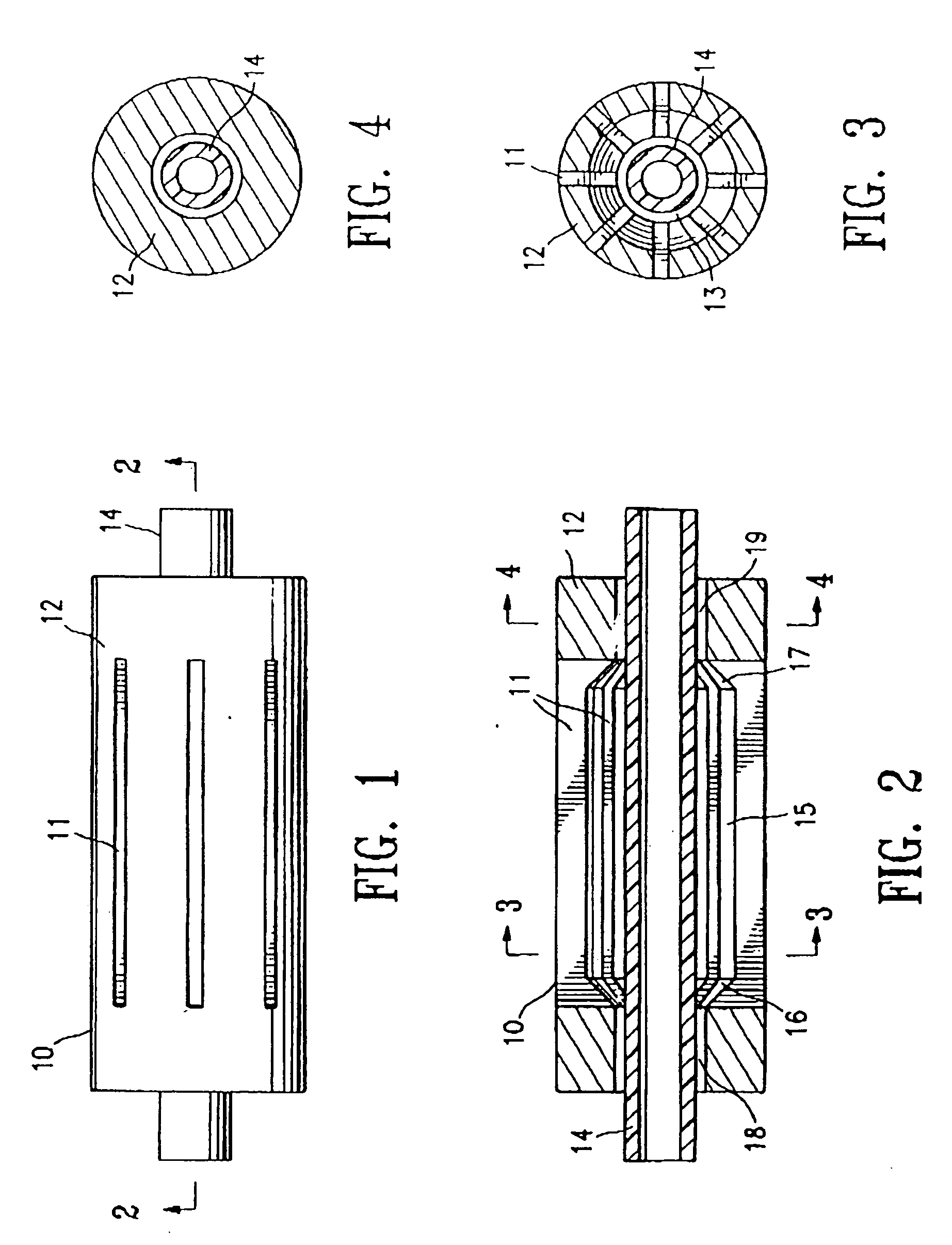
[0029]FIG. 1 illustrates a mold 10 which embodies features of the invention having channels 11 in a wall 12 of the mold. The mold has an outer surface, and an inner surface which defines an interior chamber 13, as best shown in FIG. 2 illustrating a longitudinal cross section of the mold 10 of FIG. 1, taken along line 2-2, and in FIGS. 3 and 4 illustrating transverse cross sectional views of the mold of FIG. 2, taken along lines 3-3 and 4-4, respectively. A polymer tube 14 is in the mold chamber 13. In the embodiment of FIG. 1, the channels 11 are longitudinally extending slots, the entire length of which extend through the wall 12 of the mold 10 from the outer surface to the inner surface, so that the channels 11 are in fluid communication with the chamber 13, as best illustrated in FIGS. 2 and 3.

[0030] The mold chamber 13 has a central section 15, proximal and distal tapered sections 16, 17 at either end of the central section 15, a proximal end section 18 at the proximal end of ...


PUM

PropertyMeasurementUnit
widthaaaaaaaaaa
wall thicknessaaaaaaaaaa

Abstract

A method of making a catheter balloon, and a balloon formed thereby, in which a polymeric tube is radially expanded in a mold having a wall with an outer surface and an inner surface defining a chamber, and having at least a section with one or more channels in the wall. The channels result in improved transfer of heat to the polymeric tube within the chamber of the mold during blow molding of the tube to form a balloon, so that the tube is heated more quickly and evenly. One aspect of the invention is directed to a balloon having sections with improved thin walls.

Description

BACKGROUND OF THE INVENTION [0001] This invention generally relates to medical devices, and particularly balloon molds for making balloons for intravascular balloon catheters. [0002] In percutaneous transluminal coronary angioplasty (PTCA) procedures a guiding catheter is advanced in the patient's vasculature until the distal tip of the guiding catheter is seated in the ostium of a desired coronary artery. A guidewire is first advanced out of the distal end of the guiding catheter into the patient's coronary artery until the distal end of the guidewire crosses a lesion to be dilated. A dilatation catheter, having an inflatable balloon on the distal portion thereof, is advanced into the patient's coronary anatomy over the previously introduced guidewire until the balloon of the dilatation catheter is properly positioned across the lesion. Once properly positioned, the dilatation balloon is inflated with inflation fluid one or more times to a predetermined size at relatively high pres...

Claims


Application Information

Patent Timeline
Patent Type & Authority Applications(United States)
IPC IPC(8): A61M25/00B29C35/04B29C35/08B29C49/04B29C49/18B29C49/64
CPCA61M25/1029B29L2031/7542B29C35/045B29C35/08B29C49/04B29C49/18B29C49/6409B29C2049/0089B29K2023/06B29K2027/06B29K2067/00B29K2075/00B29K2077/00B29K2079/08B29K2105/258B29C35/041B29C2949/08B29C49/42394
Inventor MAHONEY, TIMOTHY P.FLICK, MICHAEL J.
Owner ABBOTT CARDIOVASCULAR
Why Eureka
Try Eureka