Low-voltage low-power high-linearity active CMOS mixer

a high-linearity, low-voltage technology, applied in the direction of demodulation, electrical equipment, transmission, etc., can solve the problems of poor power gain and noise figure, strong coupling between power and noise, and purport to enhance the linearity performance of active mixers, so as to improve the linearity of current commutating active mixers

Inactive Publication Date: 2005-06-09
MAHMOUDI FARSHEED +1
View PDF9 Cites 35 Cited by
  • Summary
  • Abstract
  • Description
  • Claims
  • Application Information

AI Technical Summary

Benefits of technology

[0014] In accordance with a third aspect of the invention there is provided a method of improving the linearity of a current commutating active mixer comprising: transforming the input voltage to a current through a transconductance amplifier, the transconductance amplifier having transconductors which compensate each other's nonlinearities resulting in a constant transconductance over a wide range of input differential voltages; down-converting the RF current to the desired IF with a mixing stage; ac-coupling the RF transconductance amplifier and the mixing stage; and converting an information bearing signal back to voltage using an IF stage.

Problems solved by technology

A typical current commutating mixer, despite its wide spread use, has a disadvantage in that it demonstrates a strong coupling between power gain, linearity and the noise figure.
This means that a reasonably high linearity, as will be called for by future mobile applications, typically results in poor power gain and noise figure.
Although these patents relate to low voltage implementations they do not purport to provide enhancement of the linearity performance for the active mixer.
Due to this characteristic even the most recent design attempts do not significantly improve the inherent noise-linearity trade-off in the RF mixer.
Previous state of the art designs either add to the complexity of the design or include unreasonable amounts of inductive degeneration.

Method used


Image

  • Low-voltage low-power high-linearity active CMOS mixer
  • Low-voltage low-power high-linearity active CMOS mixer
  • Low-voltage low-power high-linearity active CMOS mixer

Examples


Embodiment Construction

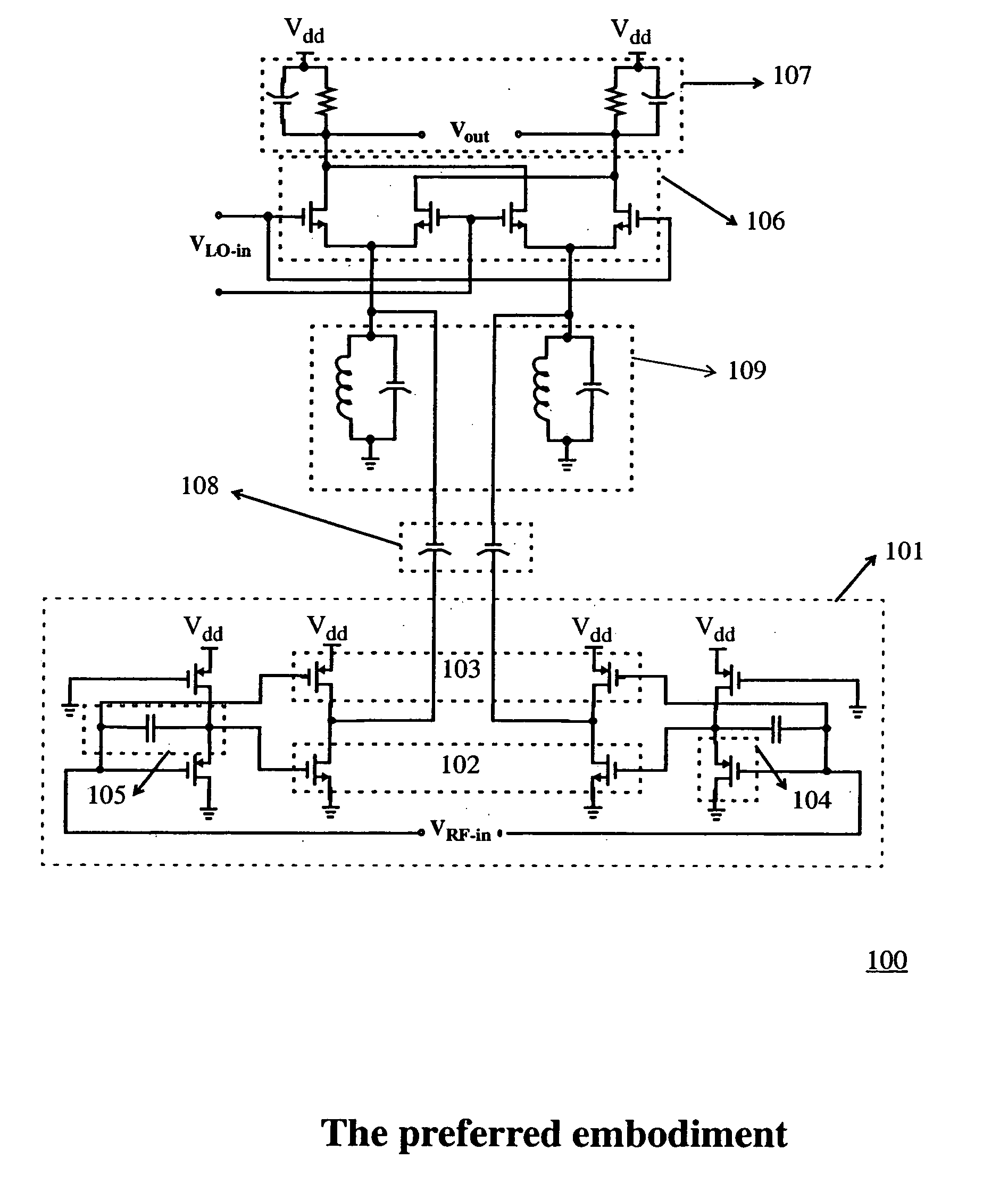
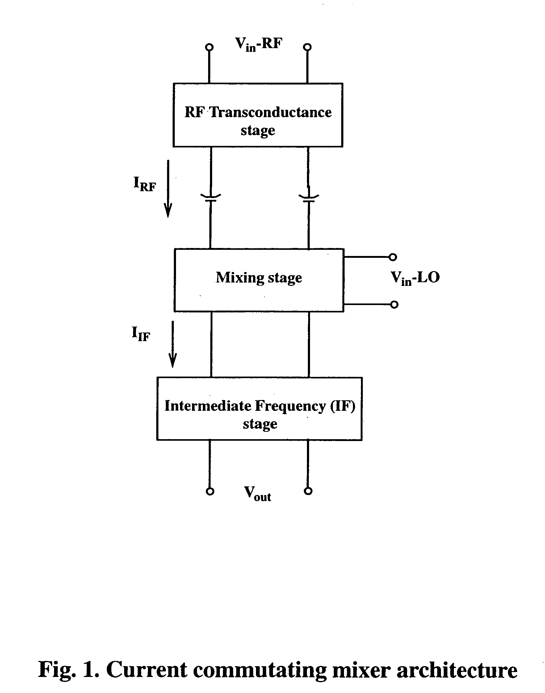
[0022] As indicated previously the basic concept of a current commutating mixer is shown in FIG. 1. The RF signal is fed to the RF transconductance stage and then to the mixing stage where it is mixed with the local oscillator signal to generate an intermediate frequency current signal which is converted to an RF voltage out at the IF stage.

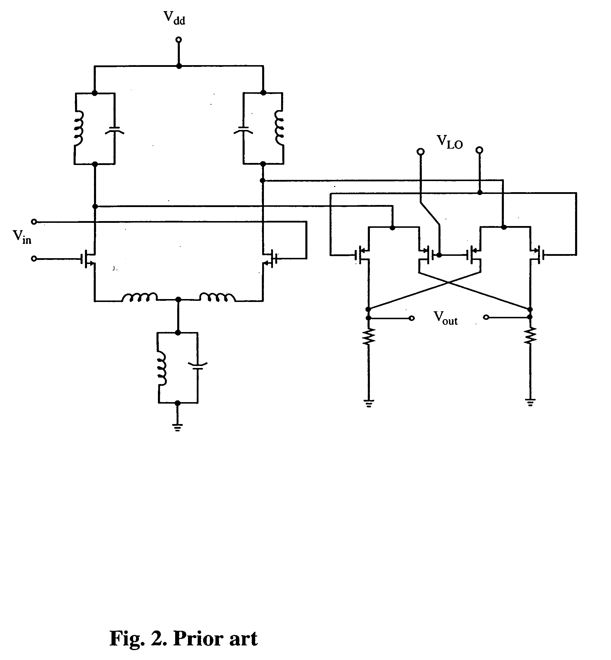
[0023]FIGS. 2 and 3 illustrate prior art attempts to generate low voltage mixers without any particular attention paid to achieving high linearity.

[0024] As discussed previously, the RF transconductor typically contributes signficantly to the non-linearity of a mixer circuit.

[0025] The mixer according to the present invention is shown generally at 100 in FIG. 4. As shown the high-linearity, low-voltage, low-power active mixer consists of an RF transconductance amplifier shown generally at 101. The novel design of RF transconductor amplifier 101 makes a significant contribution to the overall novelty of the mixer according to the present invent...


PUM


Abstract

A low voltage, low power, high linearity active CMOS mixer for radio frequency (RF) wireless communication applications consists of high linearity RF transconductor to convert the incoming RF voltage into a RF current; an ac-coupling stage to deliver the RF current to the next stage, and to block the DC signal and the flicker noise of the RF transconductor; followed by a current commutating (mixing) stage to down-convert the RF signal to the desired intermediate frequency (IF), and an IF section that converts the down-converted signal current back to voltage. The invention suggests a novel low-voltage, low-power RF mixer circuit that exhibits a high linearity in terms of IIP2 and IIP3 and is suitable for a low voltage, direct conversion receiver (DCR) which requires a relatively high IIP2. The DCR is a candidate for the fourth generation of mobile communication systems (4G).

Description

FIELD OF THE INVENTION [0001] This invention relates to RF mixers and more particularly to high linearity, low voltage, and low power mixers for applications such as mobile communications. BACKGROUND [0002] With the ever increasing demand for high bandwidth communication systems such as current mobile systems and more particularly next generation mobile communications services comes the need for systems and methods for efficiently meeting these increased demands while maintaining low voltage operations. The fourth generation (4G) mobile systems, for example, will require support for interactive multi-media services including teleconferencing, wireless Internet etc. To meet these demands current and future systems will need to support much higher bit rates while maintaining low costs. [0003] As bit rates increase the requirement for linearity, within the receiver's signal processing components in particular, becomes more important. In most current RF receivers the incoming RF signal ...

Claims


Application Information

Patent Timeline
Patent Type & Authority Applications(United States)
IPC IPC(8): H03D7/14H04B1/26
CPCH03D7/1441H03D2200/0084H03D7/1491H03D7/1458
Inventor MAHMOUDI, FARSHEEDSALAMA, C. ANDRE T.
Owner MAHMOUDI FARSHEED
Why Eureka
Try Eureka