Combustion temperature high speed detection device

Active Publication Date: 2005-06-16
MITSUBISHI HITACHIPOWER SYST LTD
View PDF7 Cites 10 Cited by
  • Summary
  • Abstract
  • Description
  • Claims
  • Application Information

AI Technical Summary

Benefits of technology

[0011] According to this aspect, even if there is a detection lag in the temperature detector, the combustion gas temperature can be detected at a high speed. The use of the so obtained data for temperature control enables high speed temperature control to be achieved.
[0012] In a second aspect of the invention, the high speed detection means of the first aspect may be phase lead processing means. According to this aspect, even if there is a detection lag in the temperature detector, the combustion gas temperature can be detected at a high speed. The use of the so obtained data for temperature control enables high speed temperature control to be achieved. By applying the phase lead processing means, moreover, a simple and effective high speed detection means can be achieved.
[0013] In a third aspect of the invention, the combustion temperature high speed detection device of the second aspect may further comprise phase lag processing means for relaxing a stepwise change in the temperature detection signal. According to this aspect, a stepwise temperature change, which is impossible in the operation of the gas turbine system is relaxed, thus making it possible to perform high-speed detection of the combustion gas temperature more suitable for the gas turbine system.
[0014] In a fourth aspect of the invention, the combustion temperature high speed detection device of the second or third aspect may further comprise first-order lag filtering means for removing a high frequency electrical disturbance, which has slipped into the temperature detection signal, from the temperature detection signal. According to this aspect, a high frequency electrical disturbance (noise component) is removed from the temperature detection signal. This makes it possible to perform high speed detection of the combustion gas temperature more suitable for the gas turbine system.
[0015] In a fifth aspect of the invention, the combustion temperature high speed detection device of the second, third or fourth aspect may further comprise temperature change filtering means for filtering out a high frequency component of the temperature detection signal. According to this aspect, a high frequency fluctuating component, which is normally unlikely for the operation of the gas turbine system, is cut out of the temperature detection signal, thus making it possible to perform high speed detection of the combustion gas temperature more suitable for the gas turbine system.
[0016] In a sixth aspect of the invention, the combustion temperature high speed detection device of the second, third, fourth or fifth aspect may further comprise disturbance filtering means including: first first-order lag filtering means with a short time constant; second first-order lag filtering means with a long time constant; and high value selecting means for selecting the higher of output values of the first and second first-order lag filtering means. According to this aspect, high speed detection of the combustion gas temperature more suitable for the gas turbine system can be performed. That is, disturbance filtering is abated on the occasion of a temperature change to a higher side, and a change in the temperature detection signal T1 is handled, if possible, as an actual change in the combustion gas temperature (rather than as disturbance) This measure can prevent damage to the combustor due to an excessive rise in the combustion temperature. At the time of a temperature change to a lower side, on the other hand, disturbance filtering is enhanced so as not to judge the combustion gas temperature overly low. This measure can prevent an excessive increase in the amount of fuel supply.

Problems solved by technology

With the gas turbine system, a lag in detection of the combustion gas temperature poses a problem.
However, the temperature is so high at this position that there is no other choice but to place the temperature detector at a downstream side of the gas turbine.
This leads to a lag in temperature detection.
Furthermore, the combustion gas is high in temperature and high in flow velocity even at the downstream side of the gas turbine.
In controlling the combustion gas temperature based on the temperature detection signal, therefore, high speed control responsive to a quick change in the combustion temperature is difficult.
If the combustion temperature becomes too high, in particular, the combustor may be damaged.
In the current situation, high speed control responsive to a rapid temperature rise is difficult because of a lag in temperature detection.
However, the lag in detection has not been fully decreased.

Method used


Image

  • Combustion temperature high speed detection device
  • Combustion temperature high speed detection device
  • Combustion temperature high speed detection device

Examples


Embodiment Construction

[0024] An embodiment of the present invention will now be described in detail with reference to the accompanying drawings, which in no way limit the invention.

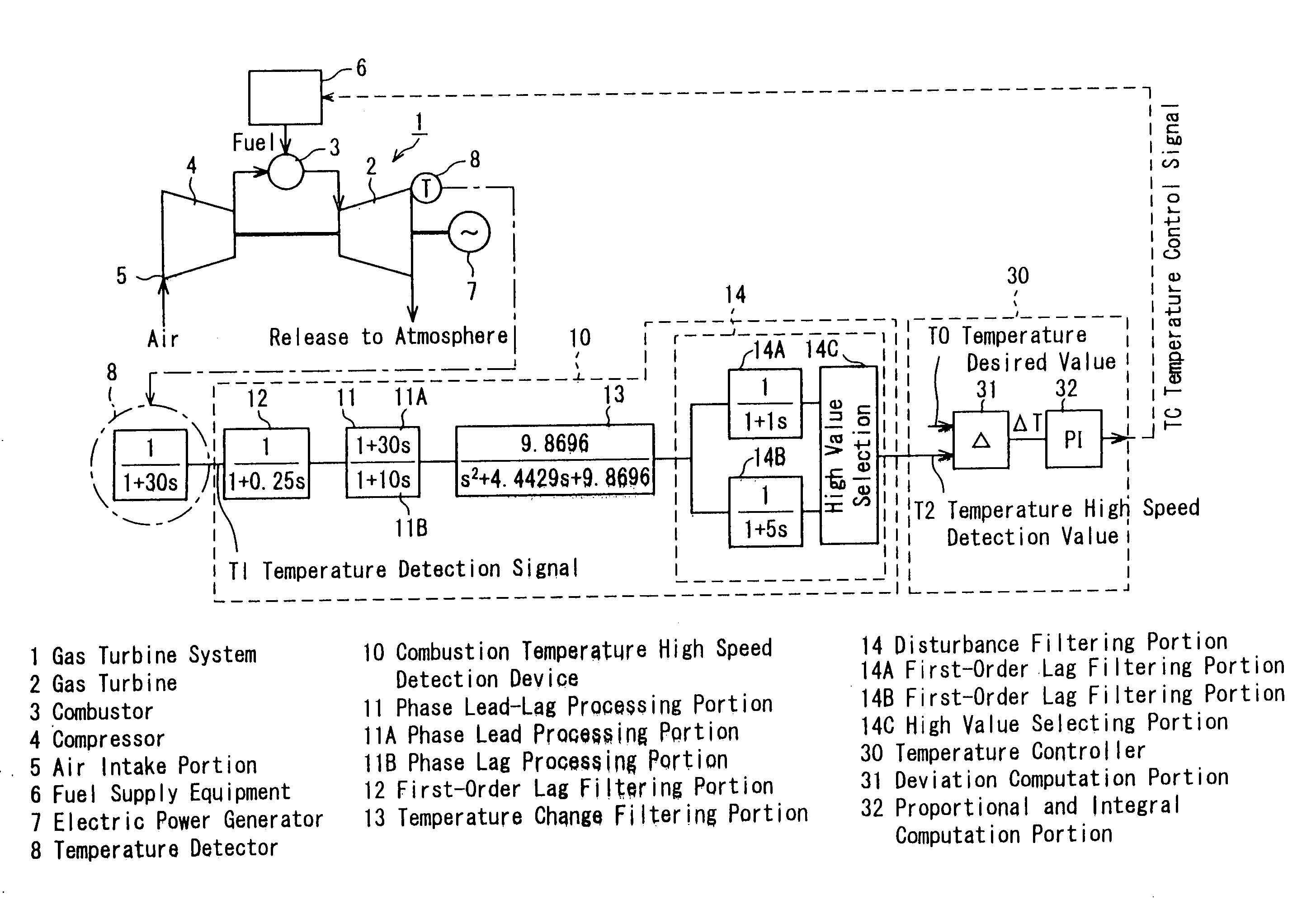
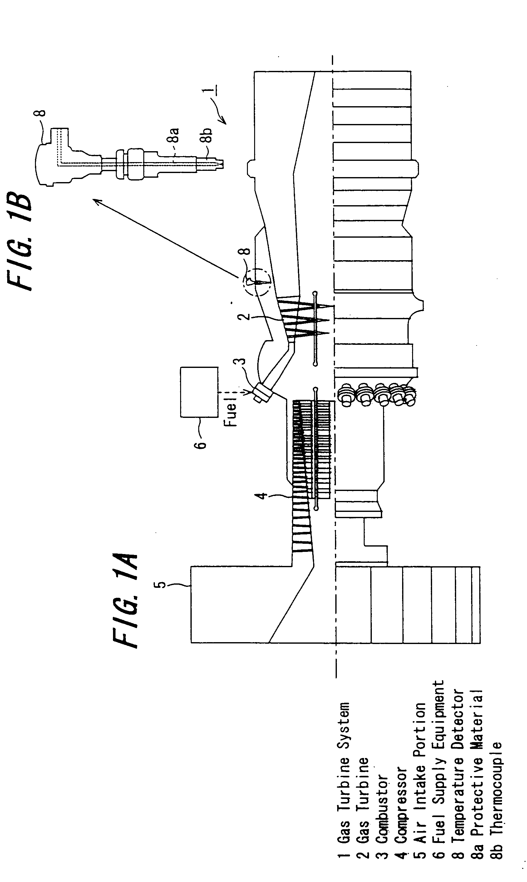
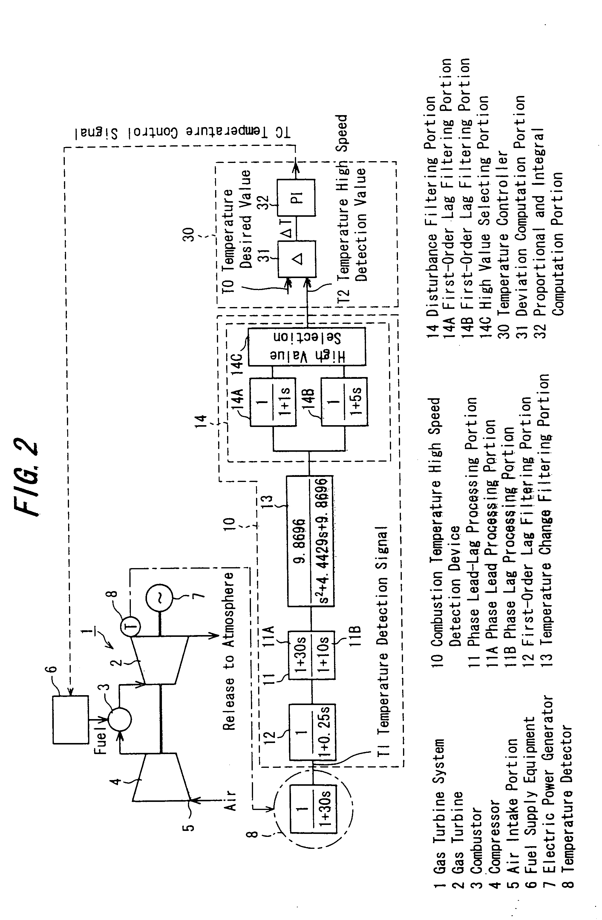
[0025] As shown in the schematic configuration drawing of FIG. 1A and the schematic view of FIG. 2, a gas turbine system 1 has a gas turbine 2, a plurality of combustors 3, and a compressor 4.

[0026] The compressor 4 has a rotating shaft coupled to a rotating shaft of the gas turbine 2. The compressor 4 is rotationally driven by the gas turbine 2 to compress air, which has been taken in from an air intake portion 5, and supply it to the combustors 3. In the combustors 3, a fuel supplied from fuel supply equipment 6 is combusted by compressed air supplied from the compressor 4. The resulting combustion gas (combustion energy) rotationally drives the gas turbine 2, which in turn rotationally drives the compressor 4, as mentioned above, and also rotationally drives an electric power generator 7 to generate electricity.

[0027] As...


PUM


Abstract

A combustion temperature high speed detection device is provided with a phase lead processing portion, thereby canceling out a detection lag of a temperature detector, and detecting the combustion gas temperature of a combustor at a high speed. The combustion temperature high speed detection device is also provided with a first-order lag filtering portion with a time constant of 0.25 second, a phase lag processing portion with a time constant of 10 seconds, a temperature change filtering portion with a cutoff frequency of 2 to 3 Hz, and a disturbance filtering portion including first-order lag filtering portions with different time constants and a high value selecting portion. Thus, high speed detection of the combustion gas temperature more suitable for a gas turbine system can be performed.

Description

[0001] The entire disclosure of Japanese Patent Application No. 2003-198913 filed on Jul. 18, 2003, including specification, claims, drawings and summary, is incorporated herein by reference in its entirety. BACKGROUND OF THE INVENTION [0002] 1. Field of the Invention [0003] This invention relates to a combustion temperature high speed detection device for detecting, at a high speed, the combustion gas temperature of a combustor, which is provided in a gas turbine system, based on a temperature detection signal from a temperature detector installed in the gas turbine system. [0004] 2. Description of the Related Art [0005] A temperature detector using a thermocouple for detecting the combustion gas temperature of a combustor, which is provided in a gas turbine system, is installed in the gas turbine system. A temperature controller of the gas turbine system provides feedback on a temperature detection signal from the temperature detector to exercise control such that the combustion g...

Claims


Application Information

Patent Timeline
IPC IPC(8): F01D21/00G01K7/00F02C9/00F02C9/28G01K7/42G01K13/02
CPCF01D21/003F02C9/28F05D2270/083F05D2270/303G01K13/02G01K2205/04G01K7/42
Inventor NAKAMURA, SHINSUKEFUJII, FUMINORIUCHIDA, SHINYATOYAMA, KOZOONO, HITOI
Owner MITSUBISHI HITACHIPOWER SYST LTD
Why Eureka
Try Eureka