Magnetoresistance effect element having a nonmagnetic intermediate layer having a two-dimensional fluctuation of resistance

a resistance element and nonmagnetic intermediate layer technology, applied in the field of magnetoresistance effect elements, can solve the problems of limiting the increase of the mr rate of change, difficult to acquire the value which exceeds 20%, and not desirable that the resistance of the element itself becomes large, etc., to achieve stably obtain, large change of resistance, and high sensitivity

Inactive Publication Date: 2005-06-16
KK TOSHIBA
View PDF17 Cites 0 Cited by
  • Summary
  • Abstract
  • Description
  • Claims
  • Application Information

AI Technical Summary

Benefits of technology

[0043] As mentioned above, according to the embodiments of the invention, a current constriction effect can be obtained by providing an oxide intermediate layer which has a two-dimensional fluctuation of electrical conductivity, for example, and thereby a large change in resistance can be attained in a CPP-type structure.
[0044] As a result, a magnetic field detection with a high sensitivity can be stably obtain ed and a magnetic head having a high output and high S / N even at a high recording density and a magnetic reproducing apparatus, and a magnetic memory of the degree of high integration can be realized with low power consumption, and the merit on industry is great.

Problems solved by technology

For this reason, it is not desirable that resistance of the element itself becomes large.
However, it is difficult to acquire the value which exceeds 20% as a MR rate of change by the conventional spin valve film.
However, also in this structure, since all electrons may not pass through the interface of a magnetic layer / nonmagnetic layer, there is a limit in increase of MR rate of change.
For this reason, it is substantially difficult to realize large MR rate of change which exceeds 20% and a practical amount of resistance change of 5 ohms-30 ohms in the CIP-SV film which has the electronic reflective layers.
However, the resistance is not large enough.
However, as mentioned above, it is needed to laminate a magnetic layer and a non-magnetism layer repeatedly by turns in order to earn resistance, and it is technically very difficult to control magnetization by CPP type MR element individually to such many magnetic layers.
For this reason, Mst increases and it becomes difficult to raise the sensitivity to a signal magnetic flux.
Thus, in spite that MR rate of change in a case of a CPP artificial lattice type film exceeds 30%, the sensitivity needed as a MR sensor for magnetic heads is not obtained.
Therefore, sensitivity required as a MR sensor for heads may not be obtained.
However, the spin valve film which can be used with high storage density which exceeds 100 Gbits / inch2 at present and which has suitable resistance and the large amount of MR change, and serves as high sensitivity magnetically is difficult to realize.

Method used


Image

  • Magnetoresistance effect element having a nonmagnetic intermediate layer having a two-dimensional fluctuation of resistance
  • Magnetoresistance effect element having a nonmagnetic intermediate layer having a two-dimensional fluctuation of resistance
  • Magnetoresistance effect element having a nonmagnetic intermediate layer having a two-dimensional fluctuation of resistance

Examples


first example

[0099] First, the first example of the invention will be explained.

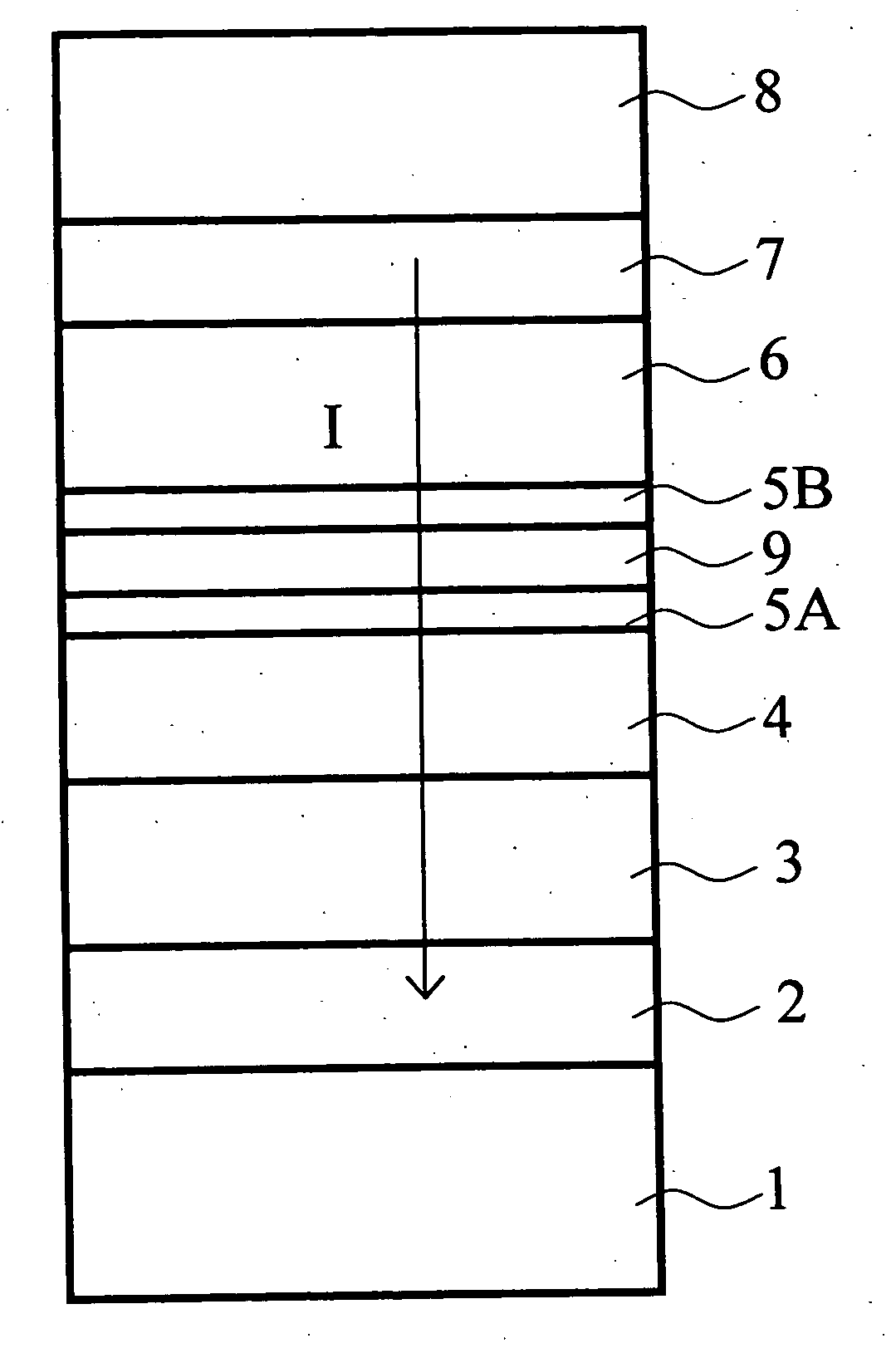
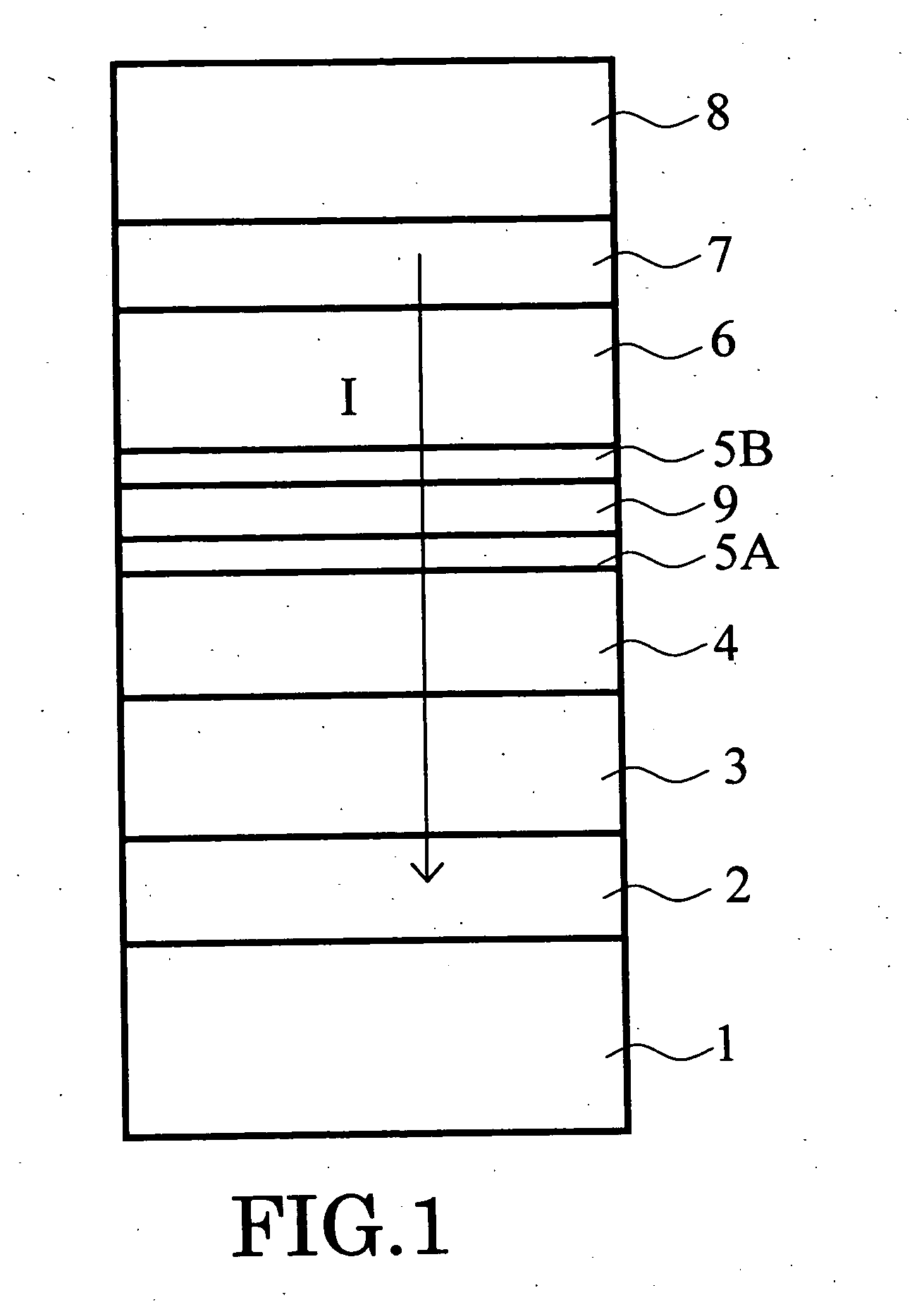
[0100] In this example, the magnetoresistance effect element of the structure expressed in FIG. 1 was manufactured with the comparative example.

[0101] That is, after forming the substrate electrode 1, the spin valve of the following film structure was formed on it: [0102] 5Ta / 2Ru / 15PtMn / 4CoFe / 1Ru / 4CoFe / intermediate-layer / 4CoFe / 1Cu / 10Ta

[0103] In the above, each number expresses the thickness (in nanometer) of the layer. This structure was formed by a DC magnetron sputtering. Then, annealing of 10 hours was performed at 270 degrees centigrade. And a patterning process was carried out to the planer shape into squares whose sizes ranged from 0.15 microns to 3 microns. Furthermore, after the surroundings of the patterned spin valve were filled up with insulators, such as alumina and a silicon oxide, the upper electrode 8 was formed, and thus the element having a structure of passing current perpendicularly to a film pl...

second example

[0125] Next, the example of the CPP type magnetoresistance effect element which can be used as a magnetic head is given and explained as the second example of the invention.

[0126]FIGS. 4 and 5 are conceptual diagrams which express typically the principal part structure of the magnetoresistance effect element concerning the embodiment of the invention. That is, these figures express the state where the magnetoresistance effect element is included in the magnetic head. FIG. 4 is a sectional view of the magnetoresistance effect element cut in parallel to the medium facing surface P which is opposite to a magnetic recording medium (not shown). FIG. 5 is a sectional view of the magnetic resistance effect element cut in the perpendicular direction to the medium opposite side P.

[0127] The magnetoresistance effect element illustrated in FIGS. 4 and 5 has a hard abutted structure. The lower electrode 12 and the upper electrode 20 are provided in the upper and lower sides of the magnetoresi...

third example

[0132] Next, a magnetic reproducing apparatus having inboard the magnetoresistance effect element of the embodiment will be explained as the third example of the invention.

[0133] That is, the magnetoresistance effect element or the magnetic head explained with reference to FIGS. 1 through 5 can be incorporated in a recording / reproducing magnetic head assembly and mounted in a magnetic reproducing apparatus.

[0134]FIG. 6 is a perspective view that shows outline configuration of this kind of magnetic reproducing apparatus. The magnetic reproducing apparatus 150 shown here is of a type using a rotary actuator. A magnetic reproducing medium disk 200 is mounted on a spindle 152 and rotated in the arrow A direction by a motor, not shown, which is responsive to a control signal from a controller of a driving mechanism, not shown. The magnetic reproducing apparatus 150 shown here may have a plurality of medium disks 200 inboard.

[0135] The medium disk 200 may be of a “lateral recording typ...


PUM

PropertyMeasurementUnit
thicknessaaaaaaaaaa
resistanceaaaaaaaaaa
total thicknessaaaaaaaaaa

Abstract

A magnetoresistance effect element comprises a magnetoresistance effect film including a magnetically pinned layer whose direction of magnetization is pinned substantially in one direction, a magnetically free layer whose direction of magnetization changes in response to an external magnetic field, and a nonmagnetic intermediate layer located between the pinned layer and the free layer; and a pair of electrodes electrically connected to said magnetoresistance effect film to supply a sense current perpendicularly to a film plane of said magnetoresistance effect film. The intermediate layer has a first layer including a first region whose resistance is relatively high and second regions whose resistance is relatively low. The sense current preferentially flows through the second regions when the current passes the first layer. Alternatively, the concentration of oxygen in the first layer may have a two-dimensional fluctuation, and a first region where the concentration of oxygen is equal to or higher than 40 atomic % and a second region where the concentration of oxygen is equal to or lower than 35 atomic % may be provided in the first layer.

Description

CROSS-REFERENCE TO RELATED APPLICATIONS [0001] This application is based upon and claims the benefit of priority from the prior Japanese Patent Application No. 2002-093358, filed on Mar. 28, 2002; the entire contents of which are incorporated herein by reference. BACKGROUND OF THE INVENTION [0002] This invention relates to a magnetoresistance effect element, a magnetic head, a magnetic reproducing apparatus, and a magnetic memory and more particularly, to a magnetoresistance effect element which has a structure where a sense current is passed perpendicularly to a film plane of the magnetoresistance effect film, and to a magnetic head using the same, a magnetic reproducing apparatus and a magnetic memory. [0003] In a certain kind of ferromagnetic substance, a phenomenon in which resistance changes according to strength of an external magnetic field is known, and this is called the “magnetoresistance effect.” This effect can be used for detection of an external magnetic field, and suc...

Claims


Application Information

Patent Timeline
Patent Type & Authority Applications(United States)
IPC IPC(8): G11B5/39H01F10/32H01L43/08
CPCB82Y10/00B82Y25/00G11B5/3903G11B5/3909G11B2005/3996H01F10/3259H01F10/3268H01L27/224H01L27/228H01L43/08H01F10/3254H10B61/10H10B61/22H10N50/10
Inventor KOUI, KATSUHIKOYOSHIKAWA, MASATOSHITAKAGISHI, MASAYUKISAHASHI, MASASHISAKAKUBO, TAKEOIWASAKI, HITOSHI
Owner KK TOSHIBA
Why Eureka
Try Eureka