Hot water apparatus

Inactive Publication Date: 2005-06-23
PALOMA IND LTD
View PDF4 Cites 15 Cited by
  • Summary
  • Abstract
  • Description
  • Claims
  • Application Information

AI Technical Summary

Benefits of technology

[0026] Further, in the hot water apparatus according to the third aspect having the above-mentioned configuration, after drain generated at a low temperature portion of the heat exchanger is received by a drain receiving and evaporating unit, it is guided to the side facing a high temperature portion of the heat exchanger. While the drain is guided, the exhaust gas prompts the evaporation of the drain, and therefore, it is possible to evaporate drain more efficiently.
[0027] In the hot water apparatus according to the four

Problems solved by technology

That is, the temperature of the heat exchanger becomes colder with being close to its water entrance side, resulting that drain is often generated at the water entrance side.
According to the above, at the water exit side of the heat exchanger hot exhaust gas is discharged wastefully even if more heat exchange could be performed without generating drain.
Then, a drain neutralization apparatus is required, and thus the cost is fairly expensive.
Moreover, it is necessary to change a neutralizing agent used in the neutralization apparatus periodically, which deteriorates utility of the condensing water heater.
According to this water heater, the same amount of heat as that of latent heat recovered by the secondary heat exchanger

Method used


Image

  • Hot water apparatus
  • Hot water apparatus
  • Hot water apparatus

Examples


Embodiment Construction

[0031] To clarify the above-described configuration and operation of the present invention, the preferred embodiment of the present invention will be explained below.

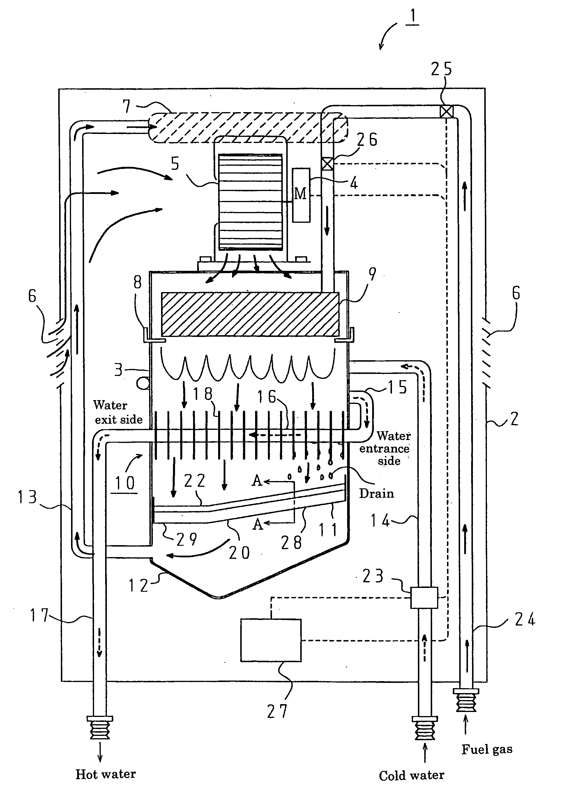
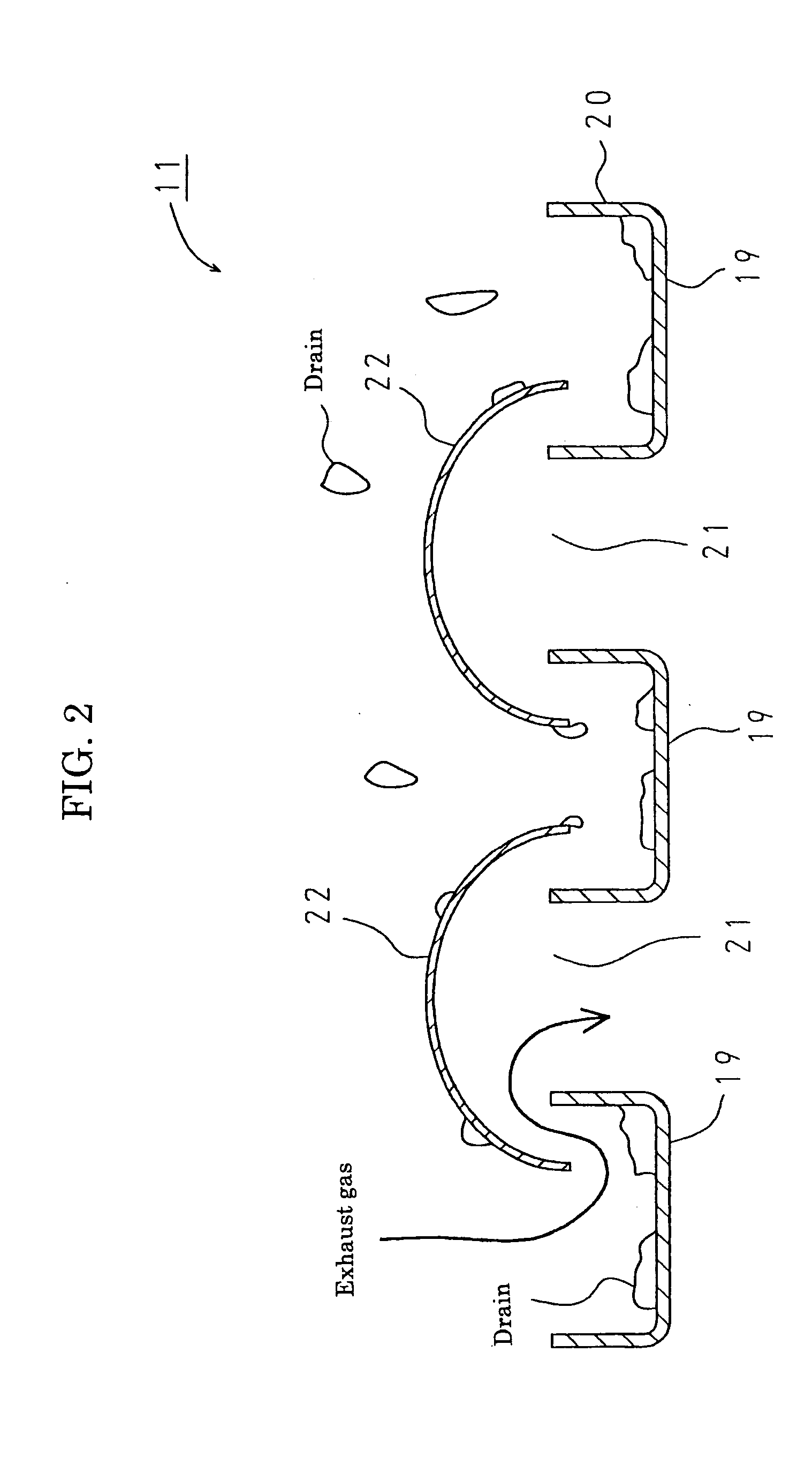
[0032] As shown in FIG. 1, a water heater 1 as one embodiment of the present invention includes a main body 2 having a combustion chamber 3 above which a blower 5 connected with a DC motor 4 is provided. The main body 2 has an inlet 6 for supplying air for combustion and an outlet 7 for discharging exhaust gas to the upside of the inlet 6.

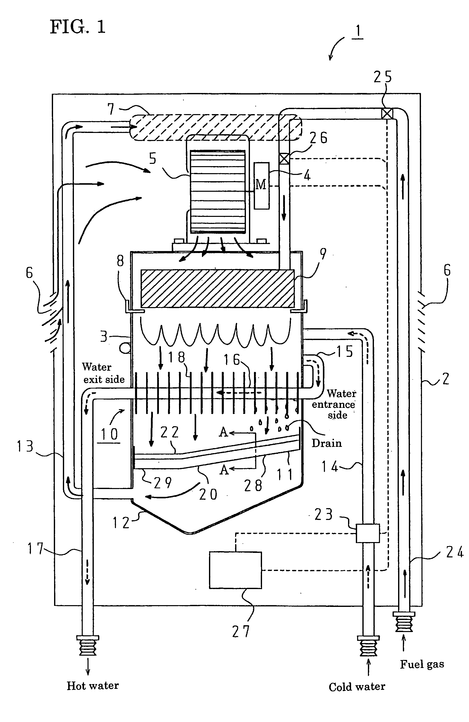
[0033] In the combustion chamber 3, provided are, from the upstream side, a burner 9 disposed on an installation plate 8 with a flame port reversed for burning mixed gas made of fuel gas and primary air from the blower, a heat exchanger 10 of the fin tube type for recovering sensible heat of exhaust gas from the burner 9 and latent heat of drain generated therein, a drain evaporator 11 for receiving and evaporating drain, and an exhaust gas hood 12 for discharging exhaust gas which h...


PUM


Abstract

A hot water apparatus is provided in which heat recovery is performed as much as possible allowing drain to be generated and excellent heat efficiency is achieved without providing a plurality of heat exchangers by effectively evaporating generated drain. In a water heater 1, the drain evaporator 11 is disposed inclining so that its side facing the high temperature portion of the heat exchanger 10 is at a lower position. The generated drain drops on the drain receiver guiding portion 28, and moves by its own weight to the side facing the high temperature portion. Then the drain is heated and evaporated. In this evaporation, the same amount of heat as that of recovered latent heat is discharged to the exhaust gas, however, sensible heat can be recovered as much as possible without limiting drain generation in the heat exchanger 10.

Description

BACKGROUND OF THE INVENTION [0001] This application claims the benefit of Japanese Patent Application Number 2003-421824 filed Dec. 19, 2003, the entirety of which is incorporated by reference. [0002] 1. Field of the Invention [0003] The present invention relates to a hot water apparatus, for example a water heater, which includes a heat exchanger for heating flowing water by combustion heat of a burner. [0004] It should be noted that in the following explanation “exhaust gas” means not only exhaust gas passing through a heat exchanger but also hot exhaust gas generated by burner combustion before heat exchange. [0005] 2. Description of Related Art [0006] Generally, as an example of a hot water apparatus, a water heater has a heat exchanger with which a cold water supply pipe and a hot water outlet are connected, and a burner which heats the heat exchanger. With this configuration, the heat exchanger heats flowing water by combustion exhaust heat from the burner, and hot water is di...

Claims


Application Information

Patent Timeline
IPC IPC(8): F23L17/14F24H8/00F24H9/00
CPCF24H8/006Y02B30/00F24H8/00
Inventor KOBAYASHI, TOSHIHIRO
Owner PALOMA IND LTD
Why Eureka
Try Eureka