Substrate with micro-via structures by laser technique

a laser technique and substrate technology, applied in the field of substrates, can solve problems such as electromagnetic interference (emi), and achieve the effect of reducing noise interferen

Active Publication Date: 2005-06-23
ADVANCED SEMICON ENG INC
View PDF3 Cites 26 Cited by
  • Summary
  • Abstract
  • Description
  • Claims
  • Application Information

AI Technical Summary

Benefits of technology

[0012] It is therefore an object of the invention to provide a substrate to which a laser technique is applied. The substrate with micro-via structure can keep the coupling ca

Problems solved by technology

The reflection of high-speed signals and the noise interferences

Method used


Image

  • Substrate with micro-via structures by laser technique
  • Substrate with micro-via structures by laser technique
  • Substrate with micro-via structures by laser technique

Examples


Embodiment Construction

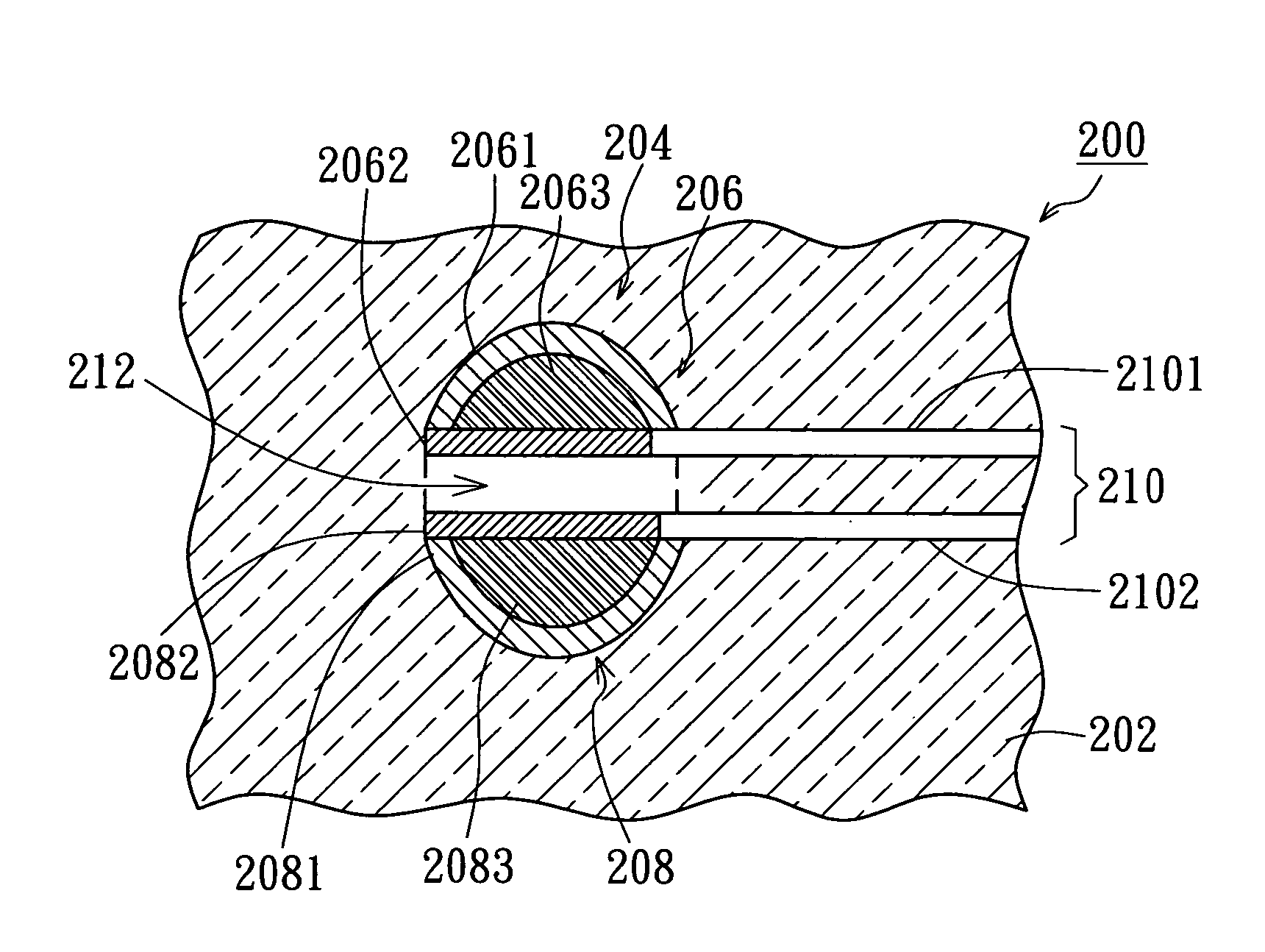
[0020] Referring to FIG. 2A and FIG. 2B, FIG. 2A is a top view of a substrate to which a laser technique is applied according to the preferred embodiment of the invention, and FIG. 2B is a three-dimensional view of a substrate to which a laser technique is applied according to the preferred embodiment of the invention. The substrate with a micro-via structure includes a substrate 200, a micro-via structure 204, and a differential signal pair 210. The substrate 200 has a signal layer 202, and the micro-via structure 204 disposed on the substrate 200 includes a first conductive column 206, and a second conductive column 208.

[0021] The first conductive column 206 includes a first cambered conductive layer 2061, a first flat conductive layer 2062, and a first dielectric layer 2063. The first dielectric layer 2063 is enclosed between the first cambered conductive layer 2061 and the first flat conductive layer 2062 to form a structure like a sandwich.

[0022] The second conductive column ...


PUM


Abstract

A substrate to which a laser technique is applied includes a signal layer, a micro via structure, and a differential signal pair. The micro via structure is divided into a first conductive column and a second conductive column after a laser-cutting step. The first conductive column includes a first flat conductive layer, and the second conductive column includes a second flat conductive layer. A first trace of the differential signal pair is parallel to and electrically connected to the first flat conductive layer. A second trace of the differential signal pair is parallel to and electrically connected to the second flat conductive layer. The distance between the first trace and the second trace is the same as the distance between the first flat conductive layer and the second flat conductive layer. The reflection of high-speed signals and the noise interferences can be reduced.

Description

[0001] This application claims the benefit of Taiwan application Serial No. 92136045, filed Dec. 18, 2003, the subject matter of which is incorporated herein by reference. BACKGROUND OF THE INVENTION [0002] 1. Field of the Invention [0003] The invention relates in general to a substrate to which a laser technique is applied, and more particularly to a substrate applied to high frequency field. [0004] 2. Description of the Related Art [0005] Micro-via on a substrate can be categorized by blind via, buried via and through via. Conventionally, the micro-via, of which the bore diameter is larger than 200 μm, is formed by mechanically drilling and others are formed by a laser technique. [0006] The conventional laser technique is using a laser with an optical system to work on a target workpiece. A pulsed laser beam can be focused on the target workpiece by a mirror or a prism, and the density of the laser power ranges from 105 to 1015 Watts per square centimeter (W / cm2). Such high laser ...

Claims


Application Information

Patent Timeline
IPC IPC(8): H05K1/02H05K1/11H05K3/00H05K3/02H05K3/40
CPCH05K1/0237H05K1/115H05K3/0038H05K3/027H05K2201/09645H05K2201/0347H05K2201/09236H05K2201/09509H05K2201/0959H05K3/403
Inventor CHIU, CHI-TSUNG
Owner ADVANCED SEMICON ENG INC
Why Eureka
Try Eureka