Cutting tool and a method for the manufacture thereof

a technology of cutting tools and manufacturing methods, applied in the direction of manufacturing tools, tool workpiece connection, twisting drills, etc., can solve the problems of high material consumption, extra large space requirements, and the tendency of the tool to be set in vibration, and achieve the effect of reducing the tool length

Inactive Publication Date: 2005-06-23
SANDVIK INTELLECTUAL PROPERTY AB
View PDF7 Cites 7 Cited by
  • Summary
  • Abstract
  • Description
  • Claims
  • Application Information

AI Technical Summary

Benefits of technology

[0006] In a first aspect, the present invention aims at obviating the above-mentioned drawbacks in previously known cutting tools of rotatable type, such as drills and milling cutters, and at providing an improved tool as well as an improved method for the manufacture of cutting tools. Thus, a primary object of the invention is to create conditions for welding together two metallic parts included in a cutting tool, in particular parts of steel, with high accuracy so far that the inevitable heat release during a welding operation must not lead to any deformations or material changes of the type that could dislodge the two parts from an exact, predetermined set position in relation to each other. An additional object is to enable realization of a welded joint, which by virtue of the position thereof in the tool can be utilized in an optimal way in respect of the capacity thereof to transfer forces between the two tool parts. Another object, related to rotatable cutting tools, such as drills and milling cutters, is to provide a tool having a minimal length and simultaneously maintained or even improved strength and rigidity, with the utmost intention that the tool during operation should give improved machining precision.
[0011] The invention is based on the idea to apply a shim in a gap between two tool parts that should be welded together, which shim has a predetermined and substantially invariable shape corresponding to the shape of the gap, and which in a cool state is welded along the periphery thereof by means of at least one laser beam, which at a considerable speed is caused to be moved along the shim, the laser beam during the movement thereof in relation to the shim and surrounding portions of the tool parts melting the metal in the shim and the tool parts, respectively, in very limited, almost point-like areas, the size of which is determined by the diameter of the beam (spot size). In such a way, welding and the ensuing heat release take place very locally in a point area, which quickly is moved along the shim; something which ensures that heat deformations, heat embrittlement and the like, do not arise in the interfaces or contact surfaces between the shim and the tool parts. During experiments that form the basis of the invention, it has accordingly been possible to observe that the tool immediately after finalized welding is so cool that the weld quite easily could be touched by a hand. Applied to a rotatable cutting tool, the invention can in an advantageous way be utilized with the purpose of reducing the tool length, at the same time as the strength of the tool in respect of the capacity of transmission of force or torque in an interface between two composed parts, e.g. a coupling part and a drill shank, not only is maintained but even can be improved.

Problems solved by technology

Besides a great dead weight, high consumption of material in the manufacture and extra great space requirements in connection with storage and transportation, the great length of the drilling tool has meant a tendency of the tool to be set in vibration because this phenomenon easier arises the longer and slender the same is.
Tests with MIG welding as well as TIG welding have, however, turned out to be unfruitful, among other things, as a consequence of hydrogen embrittlement in the interface between the components and mediocre or unacceptable precision, so far that the exact positioning of the cutting inserts in relation to the coupling part was lost.
However, no one of the welding procedures, which are accounted for in the same publications, utilizes the inventive principle of applying a separate, metallic shim in a gap opening peripherically, which shim is of a predetermined and invariable shape, and then by means of a quickly movable laser beam weld the periphery of the shim exposed outward.

Method used


Image

  • Cutting tool and a method for the manufacture thereof
  • Cutting tool and a method for the manufacture thereof
  • Cutting tool and a method for the manufacture thereof

Examples


Embodiment Construction

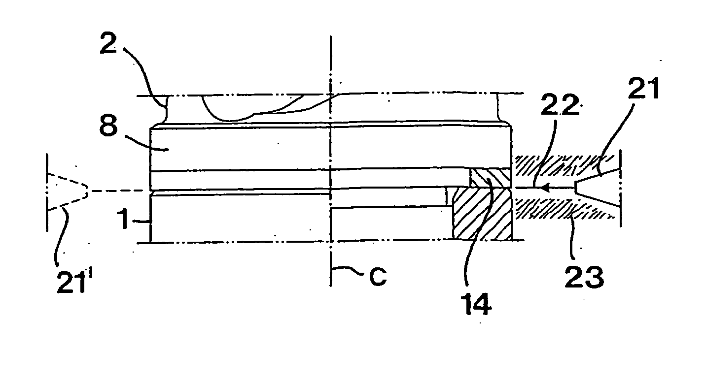
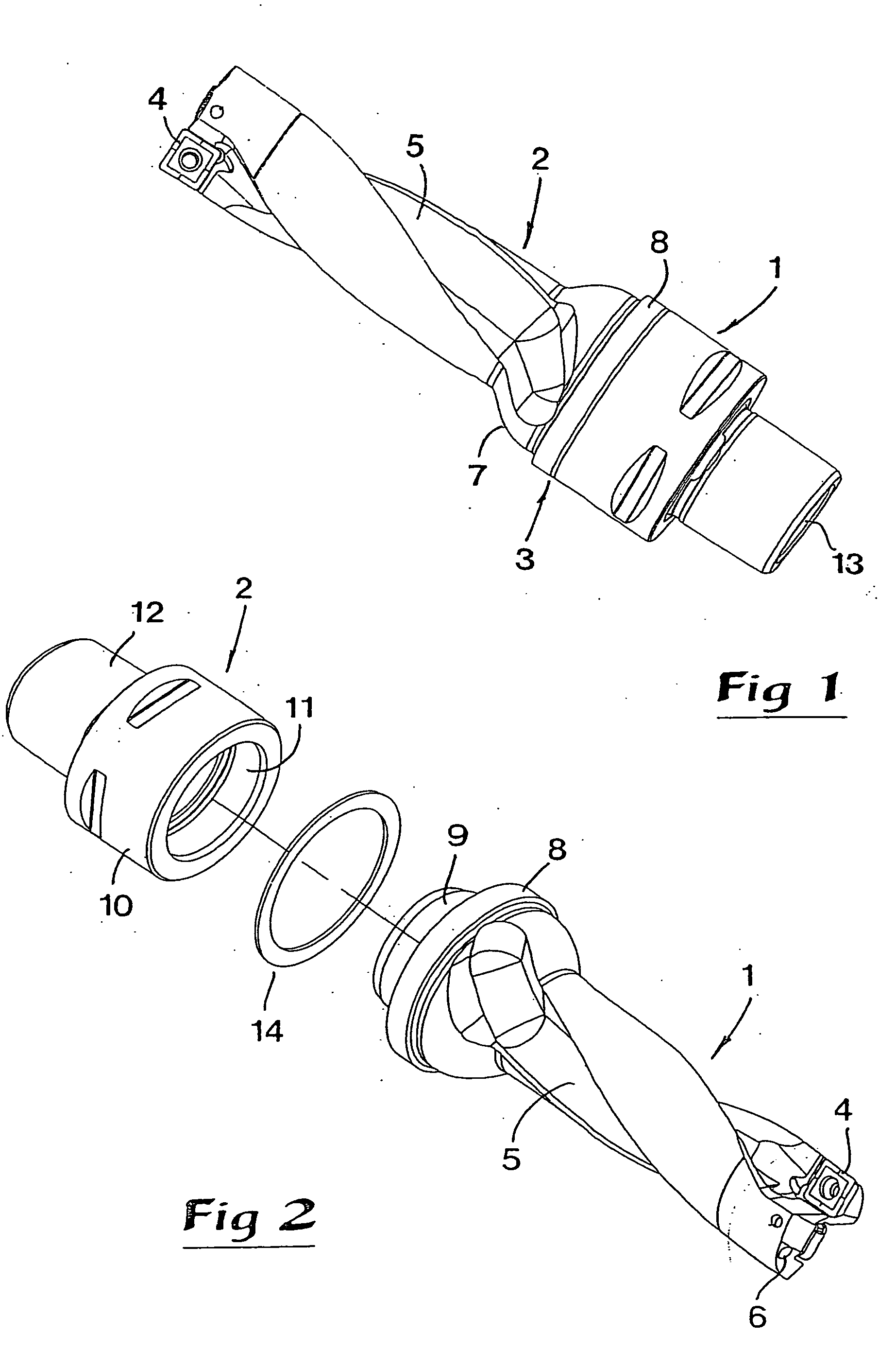
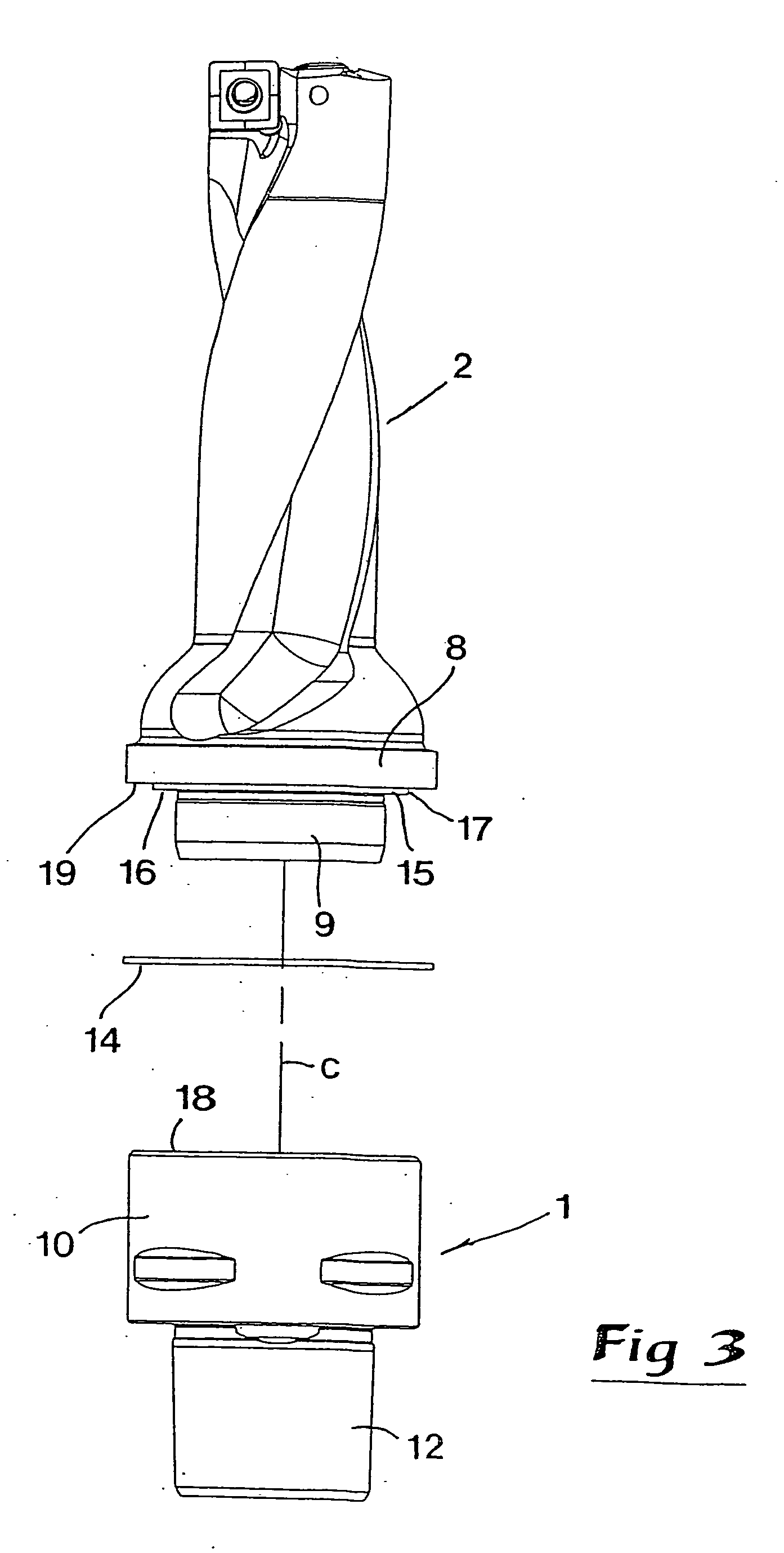
[0024] As has been mentioned by way of introduction, the problems that form the basis of the present invention are primarily associated with rotatable cutting tools, one type of which, viz, a drill, is represented in FIGS. 1-5. Said drill includes a coupling part 1, as well as a second part in the form of a shank 2 permanently united to the same via an interface 3. The shank 2 has a cylindrical, long narrow basic shape and is at the free, front end thereof formed with seatings or so-called insert pockets for releasable, replaceable cutting inserts 4. In the envelope surface of the shank, chip channels 5 are formed for evacuation of chips, which are separated by the cutting inserts 4. Internally in the shank, there are also cooling-liquid channels 6, which mouth in the tip of the shank and have the purpose of cooling the cutting inserts. At the rear end thereof, the shank transforms via a successively thickened transition portion 7 in a collar 8, the envelope surface of which is cyli...


PUM

PropertyMeasurementUnit
relative speedaaaaaaaaaa
diameteraaaaaaaaaa
speedaaaaaaaaaa

Abstract

A tool for chip-removing machining includes first and second metallic parts, and a metallic shim disposed within a gap between those parts. An outer periphery of the shim is exposed. A laser welding procedure is performed around the exposed outer periphery of the shim to weld the shim to the first and second parts. The procedure involves positioning a welder in a first position to weld the shim to one of the first and second parts, and then repositioning the welder to a second position to weld the shim to the other of the first and second parts.

Description

[0001] The present application claims priority under 35 U.S.C. § 119 to Patent Application Serial No. 0302728-1 filed in Sweden on Oct. 16, 2003, the content of which is hereby incorporated by reference. TECHNICAL FIELD OF THE INVENTION [0002] In a first aspect, this invention relates to a method for the manufacture of tools that are intended for chip-removing machining, which tools comprise two metallic parts permanently united via an interface. In a second aspect, the invention also relates to a tool, intended for cutting or chip-removing machining of primarily metal, of the type that comprises a metallic coupling part and a second metallic part permanently united to the same via an interface. PRIOR ART [0003] Tools of the above generally mentioned kind are found within all three main areas of the field of cutting machining, i.e., drilling, milling and turning. Within the two first-mentioned areas, the tools are of a rotary character and useful for the machining of fixed as well a...

Claims


Application Information

Patent Timeline
Patent Type & Authority Applications(United States)
IPC IPC(8): B23B29/00B23P15/28B23B29/04B23B51/00B23B51/02B23C5/20B23K26/20B23K26/28B23K33/00B23K101/20
CPCB23B29/046B23B51/02B23B2240/16B23B2251/02B23K2201/002B23K26/28B23K26/285B23K33/00B23B2260/092B23K26/282B23K2101/002B23B51/00B23C5/20B23B29/00
Inventor NYSTROM, LEIFMATIASSON, LARSERIKSSON, KENTH
Owner SANDVIK INTELLECTUAL PROPERTY AB
Why Eureka
Try Eureka