Joint for fuel tank and method for manufacturing the same

a fuel tank and joint technology, applied in the direction of branching pipes, packaging, siphons, etc., can solve the problems of insufficient fuel non-permeability of nylon 11 or nylon 12, inferior chemical resistance of nylon 6, nylon 66, etc., to enhance fuel non-permeability, increase the adhesive strength of the joint to a modified polyolefin of the junction, and reduce the effect of moldability

Active Publication Date: 2005-06-23
PIOLAX CO LTD
View PDF3 Cites 4 Cited by
  • Summary
  • Abstract
  • Description
  • Claims
  • Application Information

AI Technical Summary

Benefits of technology

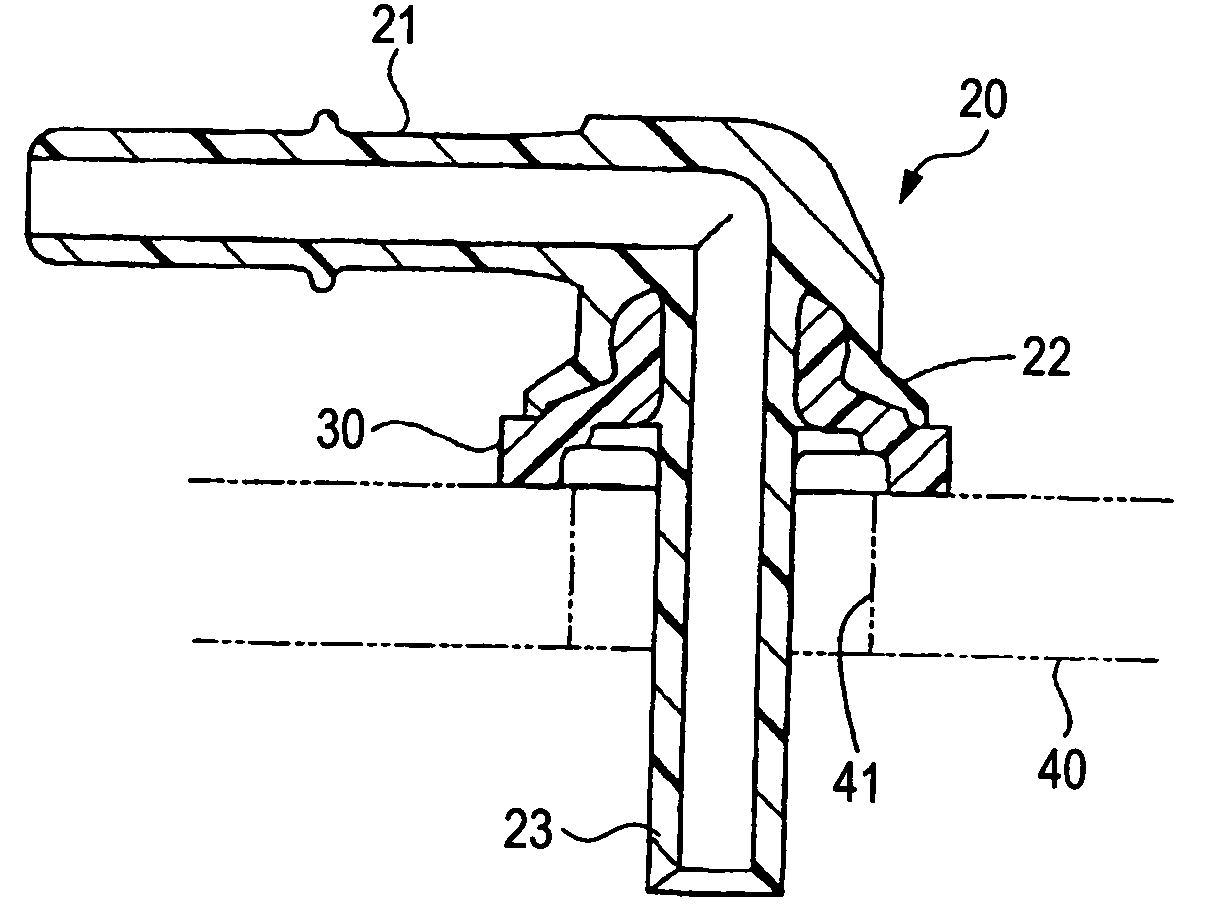
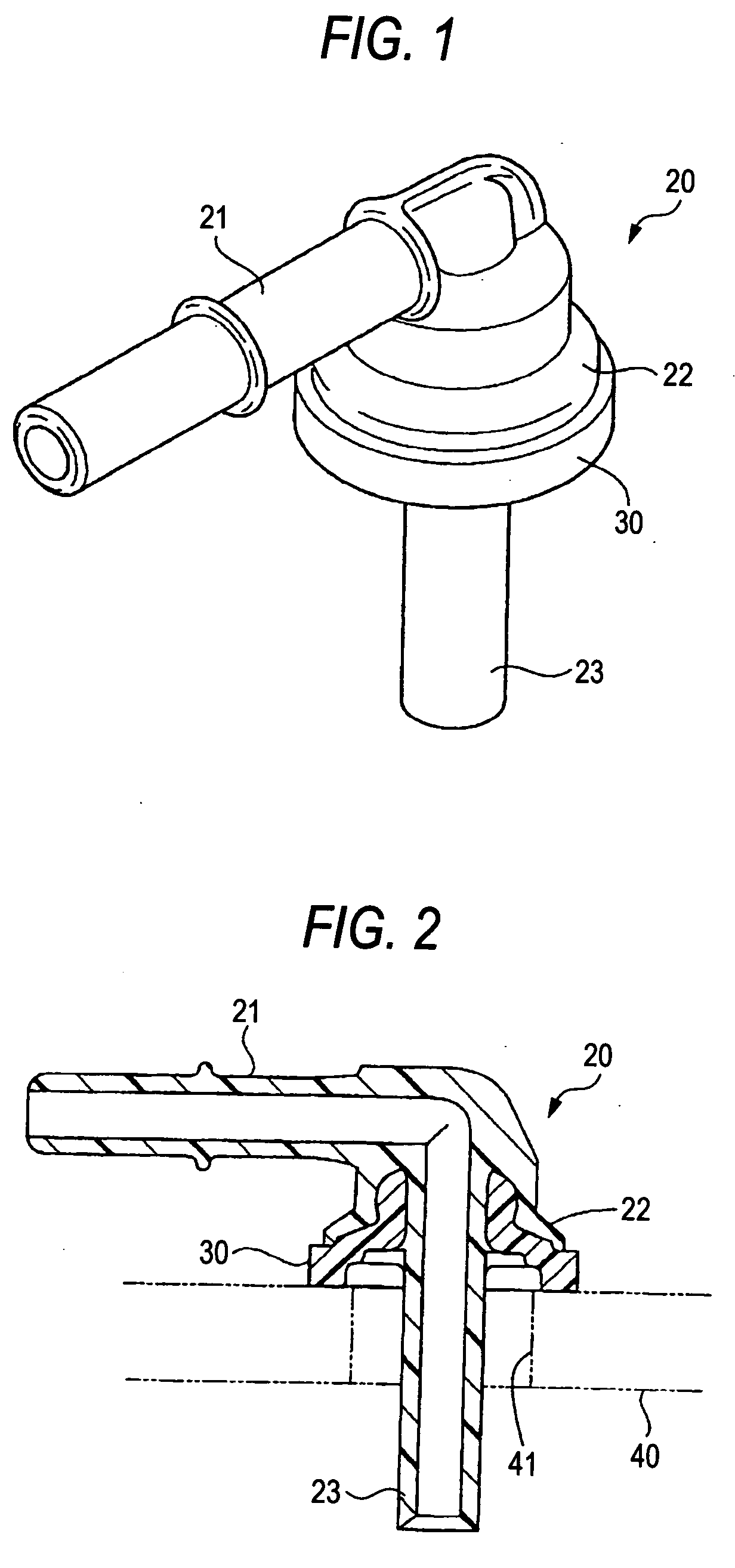
[0014] With this configuration, since the semi-aromatic polyamide is used for the joint main body, fuel non-permeability is enhanced as compared with a case where solely an aliphatic polyamide without aromatic ring is used.
[0015] In addition, since the semi-aromatic polyamide partially contains the aliphatic component, moldability is not decreased, in contrast to a case of a wholly aromatic polyamide. Furthermore, since the amount of the terminal amino group of a semi-aromatic polyamide is greater than or equal to 40 μeq / g, the amino group remains at terminals. Accordingly, adhesive strength of the joint to a modified polyolefin of the junction is increased.
[0016] Furthermore, the density of the modified polyolefin of the junction is in a range of 0.930 to 0.950 g / cm3, and the melt flow rate as measured in accordance with JIS-K7210 is in a range of 0.06 to 3.0 g / 10 minutes. Therefore, while moldability of the junction is maintained so as to allow injection molding, density of the modified polyolefin is set to a rather higher value so as to decrease fuel permeability of the junction. Consequently, fuel permeation can be reduced through not only the joint main body but also the junctions.

Problems solved by technology

However, fuel permeates not only from the fuel tank but also from a joint section connected to the fuel tank, and the amount of fuel permeating from the joint sections is not negligible.
However, of aliphatic polyamides, for instance, nylon 11 or nylon 12 is insufficient in terms of fuel non-permeability, particularly in terms of permeation-inhibition against fuel containing alcohol.
Furthermore, nylon 6, nylon 66, or the like, is inferior also in chemical resistance against calcium chloride or the like which is used as an antifreezing agent.

Method used


Image

  • Joint for fuel tank and method for manufacturing the same
  • Joint for fuel tank and method for manufacturing the same

Examples


examples 1 , 2

Examples 1, 2

[0049] Specimens for examples 1, 2 were prepared by means of insert molding with use of molding materials shown in Table 3 below. More specifically, as a primary molding process, a modified polyolefin was molded into a half size of an ASTM-type 1 dumbbell to prepare primary molded specimens. The primary molded specimen was inserted into a die, and injection molding was performed with use of a semi-aromatic polyamide as a secondary material. Accordingly, adhesion specimens equivalent to dumbbell of ASTM type 1 were obtained. In the examples, FANUC 100I was employed as a molding machine, and an ASTM abutment test piece mold was used as a die. The die for the injection molding for secondary molding was maintained at 80° C.

TABLE 3Example 1Example 2Semi-AromaticTypeMXD6PA9TPolyamideMelting Point243° C.290° C.Amount of42 μeg / g50 μeg / gTerminal AminoGroupModifiedMFR*0.30.6PolyolefinMelting Point133° C.128° C.Density0.940.935

*Measurement was performed in compliance with JIS-K7...


PUM

PropertyMeasurementUnit
thermal decomposition pointaaaaaaaaaa
densityaaaaaaaaaa
densityaaaaaaaaaa

Abstract

A joint for fuel tank is attached to an opening of a resin fuel tank. The joint includes a joint main body and a flanged junction. The flanged junction is connected to the joint main body and is weldable to a periphery of the opening of the fuel tank. The joint main body includes a semi-aromatic polyamide obtained by polymerization of source monomers containing an aromatic monomer component and an aliphatic monomer component. An amount of a terminal amino group of the semi-aromatic polyamide is greater than or equal to 40 μeq/g. The junction includes a modified polyolefin having: a density in a range of 0.930 to 0.950; and a melt flow rate as measured in accordance with JIS-K7210 in a range of 0.06 to 3.0 g/10 minutes.

Description

BACKGROUND OF THE INVENTION [0001] 1. Field of the Invention [0002] The present invention relates to a joint for fuel tank, which can be attached to, e.g., an opening of a resin fuel tank of a vehicle by means of welding, and relates to a method for manufacturing the same. [0003] 2. Description of the Related Art [0004] A variety of piping structures, such as a feeder pipe connected to an oil filler, a fuel supply pipe connected to an engine, and a vapor exhaust pipe connected to a canister, are connected by means of welding to openings of a resin fuel tank of a vehicle, as joints. [0005] Nowadays, fuel non-permeability of a fuel tank is sought. Such a fuel tank generally has a multilayer structure in which barrier resin layers being excellent in fuel non-permeability and high-density polyethylene layers are combined, with the outermost layer being formed from a high-density polyethylene, etc. [0006] Meanwhile, since a main body of the joint is made of a polyamide or the like, the o...

Claims


Application Information

Patent Timeline
Patent Type & Authority Applications(United States)
IPC IPC(8): B29C45/14B29C45/72B29C65/02B29K23/00B29K77/00B29L31/24B65D51/16F16L47/26F16L47/32F16T1/00
CPCB29C65/02B29L2031/7172B29C66/53247F16L43/008F16L47/32B60K2015/03453B29C66/1122B29C66/131B29C66/24221B29C66/71B29C66/712B29C66/7234Y10T137/3099B29K2077/10B29K2023/065
Inventor NAGAKURA, KOUICHIMATSUO, SHINICHI
Owner PIOLAX CO LTD
Why Eureka
Try Eureka