Seat mounting rail, particularly for a commercial aircraft

a technology for mounting rails and aircraft, which is applied in the direction of seating arrangements, machine supports, furniture parts, etc., can solve the problems of increasing the weight not being able to be manufactured in an economical way, and adding disadvantages, so as to improve the corrosion resistance of the entire rail, avoid significant weight increase, and excellent corrosion protection

Active Publication Date: 2005-06-23
AIRBUS OPERATIONS GMBH
View PDF18 Cites 37 Cited by
  • Summary
  • Abstract
  • Description
  • Claims
  • Application Information

AI Technical Summary

Benefits of technology

[0014] The formation of the upper rail section for securing the seats of a titanium alloy significantly improves the corrosion resistance of the entire rail. Further, the combination of an upper rail section of a titanium alloy with a lower rail section of an aluminum alloy avoids a significant weight increase while simultaneously providing an economical solution to the corrosion problem.
[0015] It has been found to be particularly advantageous if only the area of the mounting rail that is exposed to corrosion media is formed by the heavier and more expensive titanium to achieve the desired corrosion resistance while simultaneously using the lighter and less costly aluminum alloy for the mounting section. As mentioned, unnecessary material is not required for the formation of the laser weld so that the butt weld does not add any weight to the finished rail. As a result, the weight of the entire rail is only slightly higher than the weight of a rail made entirely of aluminum, or an aluminum alloy or a magnesium alloy. Yet, the corrosion resistance of the so-called crown area or top area with the slot in which the seats are mounted, provides an excellent corrosion protection just as a rail that would be made entirely of titanium. Thus, the invention has achieved an optimal compromise between the weight requirement on the one hand and the corrosion resistance requirement on the other hand, compared to a rail made entirely of titanium as well as in comparison to a rail that comprises titanium and aluminum components that require an overlap in order to connect the two components with each other, for example by adhesive bonding, riveting, or screw connections. Such overlapping areas add disadvantageously, weight to the entire rail and are not as easily manufactured in an economical way as compared to the formation of a laser butt weld. Moreover, the butt weld prevents the presence of an electrolyte such as condensation water between the two components, thereby avoiding any danger of an increased corrosion in an overlapping area.

Problems solved by technology

Such overlapping areas add disadvantageously, weight to the entire rail and are not as easily manufactured in an economical way as compared to the formation of a laser butt weld.

Method used


Image

  • Seat mounting rail, particularly for a commercial aircraft
  • Seat mounting rail, particularly for a commercial aircraft

Examples


Embodiment Construction

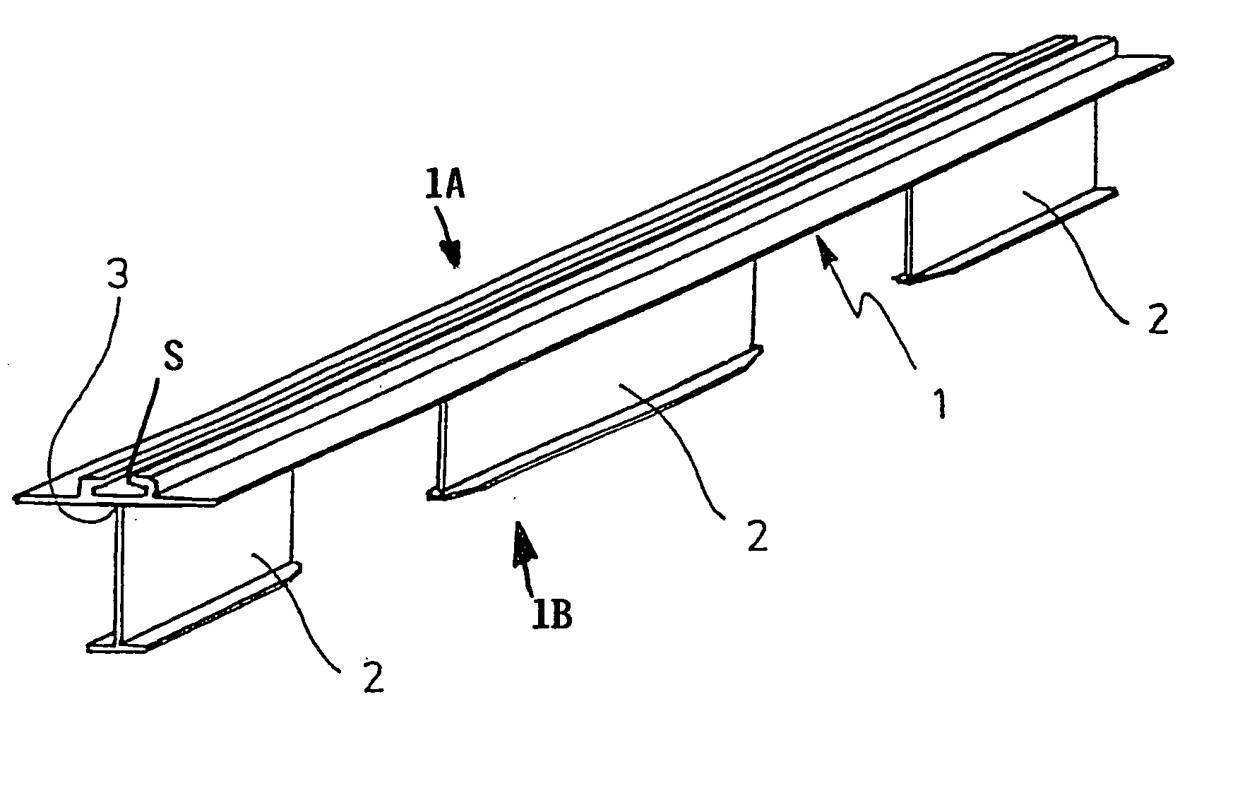
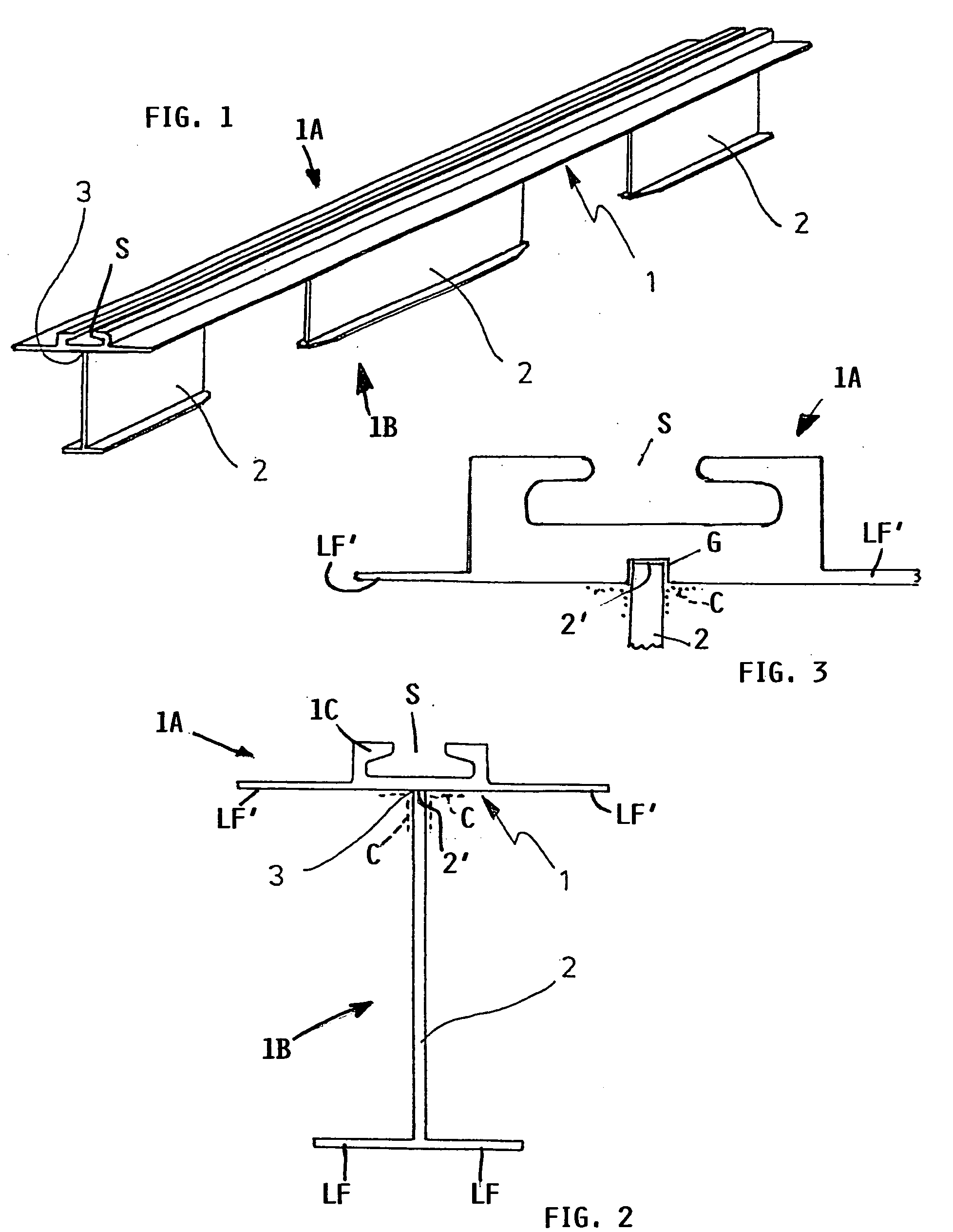
[0020] The two section or two component seat mounting rail 1 according to the invention comprises an upper rail section 1A and a lower rail section 1B which is preferably divided into a plurality of lower rail portions 2. The lower rail portions 2 are spaced from one another along the length of the rail, thereby further reducing the weight of the entire seat mounting rail 1. A bi-metallic interconnection 3 is formed between the upper rail section 1A and the lower rail portions 2, whereby the respective butt weld extends along the upper edge of the webs of the lower rail portions 2 which are also provided with lateral flanges LF for mounting the rail to or in a floor.

[0021] The chair securing upper section 1A has a central C-cross-sectional configuration 1C with lateral flanges LF′ extending away from the C-configuration 1C with the slot S facing up. Mounting holes are not shown in the C-configuration 1C. However, such holes may be provided as needed and as is conventional. The bi-m...


PUM


Abstract

A seat mounting rail for securing seats to a floor of a passenger aircraft is made of a seat securing upper section and a rail mounting lower section. Both sections are made of different metals. The upper section is made of a titanium alloy for corrosion protection. The lower rail section is made of an aluminum alloy for weight reduction. The interconnection between the two sections is made as a thermal joint for example formed as a laser weld, which is preferably a butt weld to save welding material.

Description

PRIORITY CLAIM [0001] This application is based on and claims the priority under 35 U.S.C. §119 of German Patent Application 103 60 807.9, filed on Dec. 19, 2003, the entire disclosure of which is incorporated herein by reference. FIELD OF THE INVENTION [0002] The invention relates to a seat mounting rail for securing passenger seats to the cabin floor of a commercial airliner. Such rails have a lower portion for securing to the floor and an upper portion for securing seats to the rail. Such rails may also be used for securing loads to a floor. BACKGROUND INFORMATION [0003] Mounting rails for securing passenger seats in commercial aircraft are normally standardized. One such standard defining sheets is, for example, air traffic standard LN 29 890. The standard construction of such rails includes a lower mounting rail section having an Q- or a T-cross-sectional configuration. A chair securing upper rail section includes a C-cross-sectional configuration that opens upwardly into the c...

Claims


Application Information

Patent Timeline
Patent Type & Authority Applications(United States)
IPC IPC(8): B64D11/06
CPCY02T50/46B64D11/0696Y02T50/40
Inventor ZERNER, INGO
Owner AIRBUS OPERATIONS GMBH
Why Eureka
Try Eureka