Variable wavelength ultraviolet lamp

a technology of ultraviolet lamps and wavelength bands, applied in the direction of spectral modifiers, x-ray tubes, optical radiation measurement, etc., can solve the problems of shortening the life of the bulb, not being able to select among different wavelength bands during the operation of the lamp, and having to use a different wavelength band of the bulb for each wavelength band

Inactive Publication Date: 2005-06-23
GARDNER WILLIAM G
View PDF17 Cites 46 Cited by
  • Summary
  • Abstract
  • Description
  • Claims
  • Application Information

AI Technical Summary

Benefits of technology

[0017] In view of the foregoing background, an apparatus for selectively producing one or more of a plurality of wavelength distributions of light is provided, comprising a primary light source having a primary wavelength distribution, at least one wavelength-transforming material that, in response to illumination by the primary light source produces secondary light having a wavelength distribution different from the primary light wavelength distribution, the wavelength-transforming material being disposed on a substrate external to the primary light source, and a wavelength-transforming material selection mechanism for placing at least a portion of one or more selected wavelength-transforming materials in front of the primary light source, in a selected preferred direction of light emission from the apparatus, such that the selected wavelength-transforming materials emit from the apparatus light having a wavelength distribution different from the primary light wavelength distribution.
[0018] In one preferred embodiment, the wavelength-transforming material selection mechanism comprises a rotatable cylinder surrounding the primary light source, one or more wavelength-transforming materials being disposed on a surface of the cylinder such that at least one wavelength-transforming material may be placed in front of the primary light source in a preferred direction of light emission from the apparatus by movement of the cylinder.
[0019] In another preferred embodiment, the wavelength-transforming material selection mechanism comprises a substantially flat surface comprising one or more wavelength-transforming materials disposed thereon such that one or more wavelength-transforming materials can be placed in front of the primary light source and in a preferred direction of light emission from the apparatus by movement of the substantially flat surface.
[0020] In a further preferred embodiment, the wavelength-transforming material selection mechanism comprises a flexible sheet of material having one or more wavelength-transforming materials disposed thereon, the sheet being movably disposed in front of the primary light source and in a preferred direction of light emission from the apparatus so as to select one or more wavelength-transforming materials.
[0021] These and other features and advantages of the invention will be more fully understood upon consideration of the following detailed description, taken in conjunction with the following drawings.

Problems solved by technology

However, the need to use a different UV bulb for each wavelength band is both expensive and cumbersome, and requires turning each bulb on and off more frequently, which is well known to shorten bulb life.
While this allows the production of light in more than a single wavelength band of ultraviolet light, it fails to allow for selecting among different wavelength bands during the operation of the lamp.
However, this type of bulb suffers from the disadvantages of damage to phosphors and resulting relatively short phosphor lifetimes common to many phosphors that are exposed to the harsh conditions on the inside of a low pressure mercury vapor discharge bulb.
This lamp also suffers from the further disadvantage that only a limited fraction of the total light energy emitted by the luminous mercury vapor within the bulb actually falls upon the phosphor selected.
As the phosphors are situated within the bulb, it is unavoidable that much of the light energy will be wasted because there is no way to direct it toward the desired phosphor in exclusion of phosphors placed at other locations within the bulb.
However, the system is cumbersome to use in that to shift from the wavelength band of the primary light source to light of a secondary wavelength band, a separate plate must be manually placed over the light exit port of the apparatus.
Such a device would not be very useful when portability is important as is often the case, for instance, when one wishes to view mineral specimens in the field or do forensic studies at a crime scene.
Such a device would also not be useful in applications where a user wished to use a non-manual method, such as an electric motor, to switch between various wavelength-transforming materials (phosphors).

Method used


Image

  • Variable wavelength ultraviolet lamp
  • Variable wavelength ultraviolet lamp
  • Variable wavelength ultraviolet lamp

Examples


embodiment 11

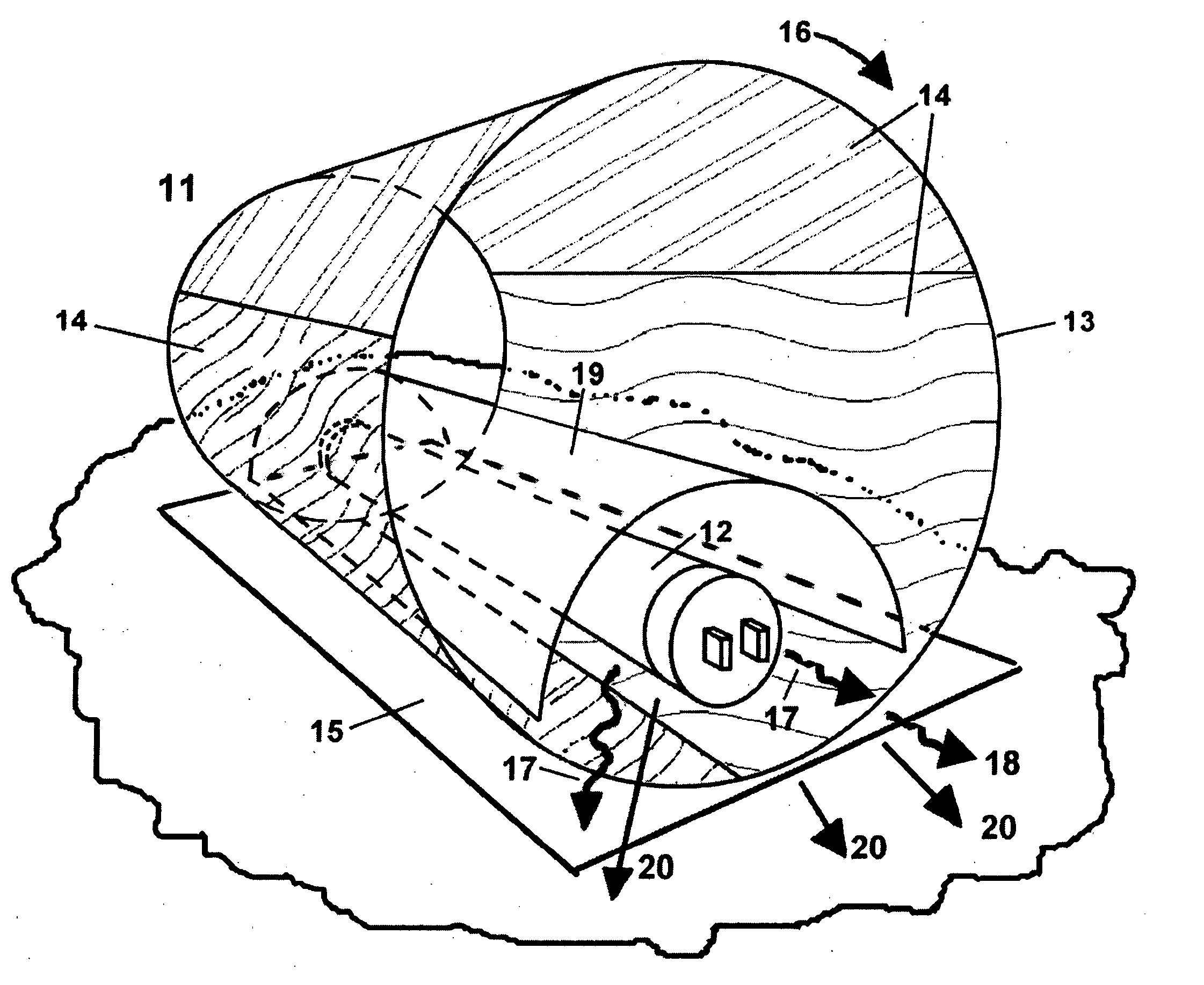
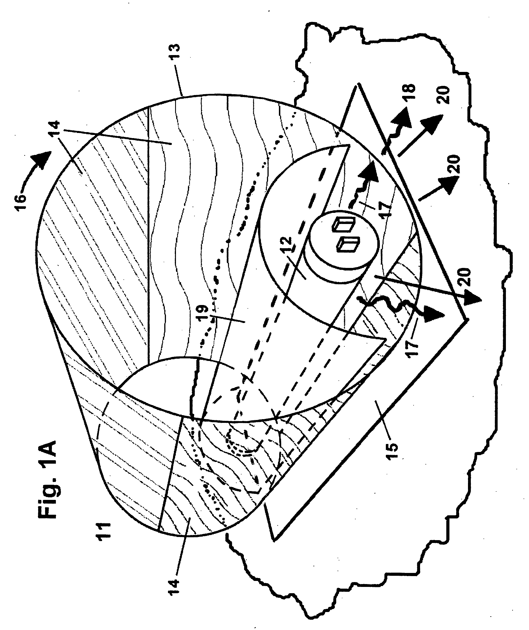
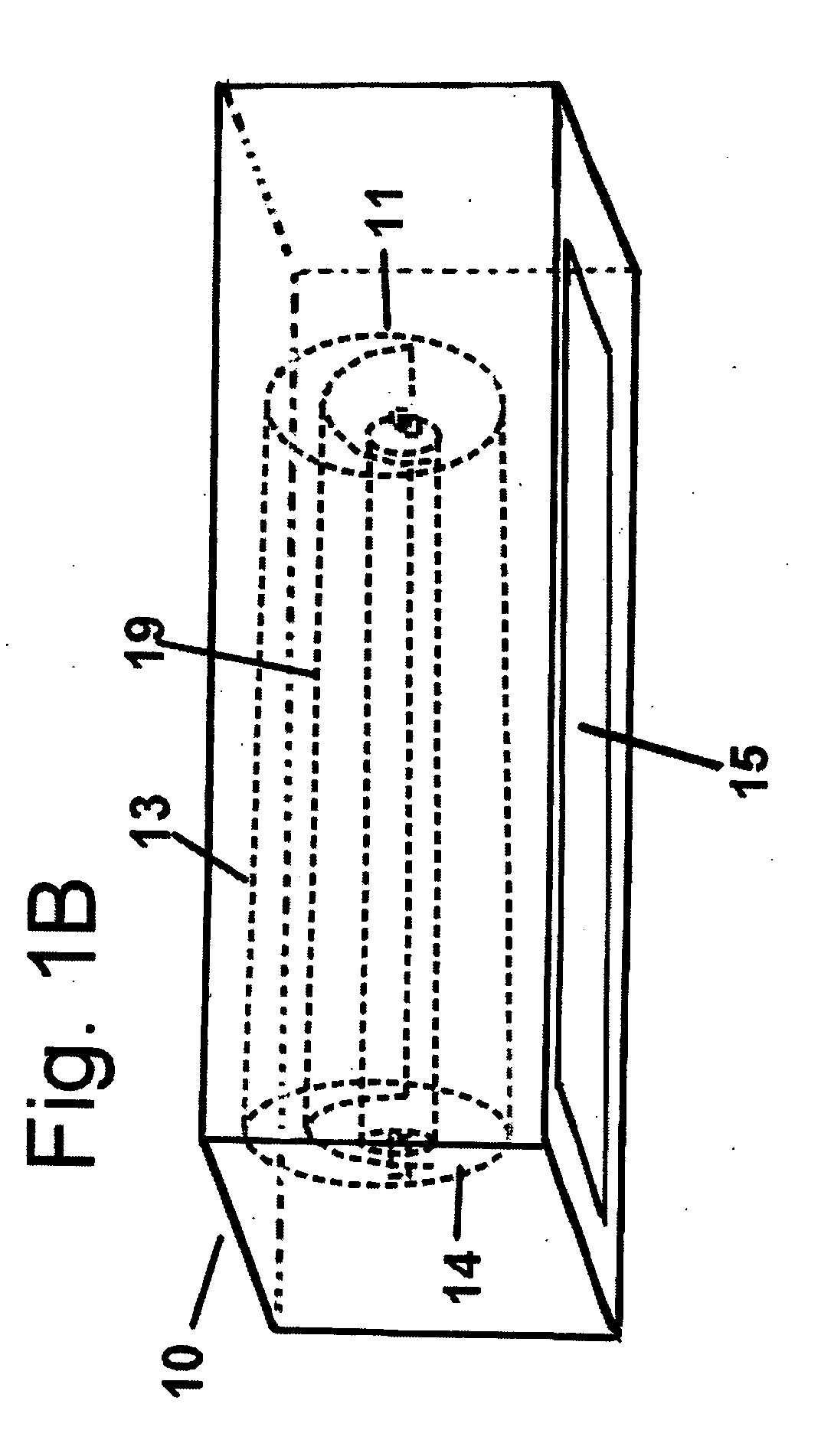
[0034] Turning now specifically to FIG. 1A, the first preferred embodiment 11 uses as a primary light source 12 a low pressure mercury vapor discharge lamp, which emits UV C light 17 largely at about 254 nanometers (nm) wavelength and which is powered by an electrical supply. Such mercury vapor discharge lamps are widely available in a variety of sizes and configurations, and are known to provide reliable and effective operation. In the embodiment of FIG. 1A the primary light source 12 is surrounded by a cylindrical substrate 13 on which are disposed a plurality of wavelength-transforming materials 14. The cylindrical substrate 13 may be rotated about its axis, as shown by arrow 16, around the primary light source 12 in such a manner as to place one or more of the wavelength-transforming materials 14 in front of the primary light source 12 in a preferred direction of light emission 20 such that light of a different distribution of wavelengths 18 may be emitted from the apparatus. Al...

embodiment 31

[0039] A second preferred embodiment, shown in FIG. 3, comprises wavelength-transforming materials that are disposed on a substantially flat unit that allows selection of the desired wavelength band of emitted light. In the second preferred embodiment 31 shown in FIG. 3, the source of primary light 12 is located behind substrate 33, which is substantially flat. A plurality of wavelength-transforming materials 34 are, in turn, disposed on substrate 33. To select one or more wavelength-transforming materials to emit light in the preferred direction of light emission 20, the substrate 33 is moved in its plane by a sliding movement, illustrated by arrow 36, such that the wavelength-transforming materials selected are positioned in front of the primary light source 12 in the preferred direction of light emission 20. Preferably a reflector unit 19 is placed so as to direct light from the primary light source toward the selected wavelength-transforming material 34 and in the preferred dire...

embodiment 41

[0041] A third preferred embodiment 41 is shown in FIG. 4. In apparatus 41 the primary light source 12 is located adjacent to substrate 43 which, in this case, is substantially flat and disc shaped and on which are disposed a plurality of wavelength-transforming materials 44 comprising sectors of the disc. Selection of one or more of the wavelength-transforming materials, or a transparent portion, is made by rotating the disc-shaped substrate in its plane, as shown by arrow 46, such that one or more of the wavelength-transforming materials selected from the plurality of wavelength-transforming materials 44 is positioned in front of the primary light source 12 in the preferred direction of light emission 20. Here also, a reflector unit 19 is preferably employed to direct light from primary light source 12 toward the selected wavelength-transforming materials 44 and in the preferred direction of light emission 20 and away from unselected wavelength-transforming materials. Preferably a...


PUM


Abstract

A variable wavelength ultraviolet lamp. An apparatus for selectively producing one or more of a plurality of wavelength distributions of light is provided, comprising a primary light source having a primary wavelength distribution, at least one wavelength-transforming material that, in response to illumination by the primary light source produces secondary light having a wavelength distribution different from the primary light wavelength distribution, the wavelength-transforming material being disposed on a substrate external to the primary light source, and a wavelength-transforming material selection mechanism for placing at least a portion of one or more selected wavelength-transforming materials in front of the primary light source, in a selected preferred direction of light emission from the apparatus, such that the selected wavelength-transforming materials emit from the apparatus light having a wavelength distribution different from the primary light wavelength distribution.

Description

BACKGROUND [0001] The field of the present invention is ultraviolet light-emitting “blacklight” lamps used in mineralogy, scientific research, and related fields. [0002] Ultraviolet lamps are widely used by geologists, rockhounds, and collectors of minerals both for identification of mineral materials and for creating the spectacular displays of fluorescence that many minerals emit when illuminated with ultraviolet light. Some minerals, which may appear drab or colorless when viewed under normal visible light, upon irradiation with ultraviolet light emit bright colored visible light that is characteristic both of the mineral in question and of the wavelength of the ultraviolet light used in the illumination. For instance, one variety of the mineral calcite found in Mexico, normally of a whitish color, will fluoresce a bright blue-white color when illuminated with short-wave ultraviolet light, a yellow color when illuminated by longer wave lengths of ultraviolet light, and a bright p...

Claims


Application Information

Patent Timeline
Patent Type & Authority Applications(United States)
IPC IPC(8): G01J3/02G01J3/10G01J3/12H01J61/42
CPCA01K63/06F21S10/02F21V9/10F21V14/006F21W2131/308F21W2131/405G01J2003/1221G01J3/02G01J3/0216G01J3/0235G01J3/0272G01J3/10G01J2003/1217F21Y2103/00F21V13/08F21V9/32
Inventor GARDNER, WILLIAM G.
Owner GARDNER WILLIAM G
Why Eureka
Try Eureka