Method of performing optical measurement on a sample

a sample and optical measurement technology, applied in the direction of optical radiation measurement, instruments, photoelectric discharge tubes, etc., can solve the problems of not being able to easily extend the method the instrument would be very bulky, and the method is not readily extendable to a large number of channels, so as to reduce the gain of the detector, reduce power requirements, and extend the life of the source

Active Publication Date: 2005-06-23
ONTO INNOVATION INC
View PDF12 Cites 13 Cited by
  • Summary
  • Abstract
  • Description
  • Claims
  • Application Information

AI Technical Summary

Benefits of technology

[0033] By processing a set of simultaneously generated detection values, the invention provides a truly parallel system which is fast, and is readily extendable to a large number of channels. This can be contrasted with the system of U.S. Pat. No. 5,757,671 in which each detector value is generated at a different time.
[0042] In the case where the radiation source is turned on and off to produce a series of radiation pulses, and the spectrum of the pulse varies with time during heating and cooling effects, the method may further include the step of closing a gate in the path of the irradiation or return beam during each radiation pulse, or reducing the gain of the detector during each radiation pulse. This provides a “spectral clean-up” of the radiation pulses by discarding unwanted signal.

Problems solved by technology

It is not possible to follow the rapidly changing modulated signal using an otherwise suitable detector.
This method is not readily extendable to a large number of channels.
Such an instrument would be very bulky.
Multichannel CCD detectors are again too slow to follow the modulation signals.

Method used


Image

  • Method of performing optical measurement on a sample
  • Method of performing optical measurement on a sample
  • Method of performing optical measurement on a sample

Examples


Embodiment Construction

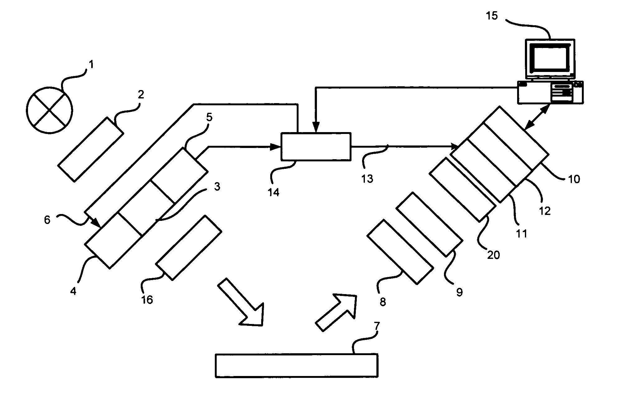
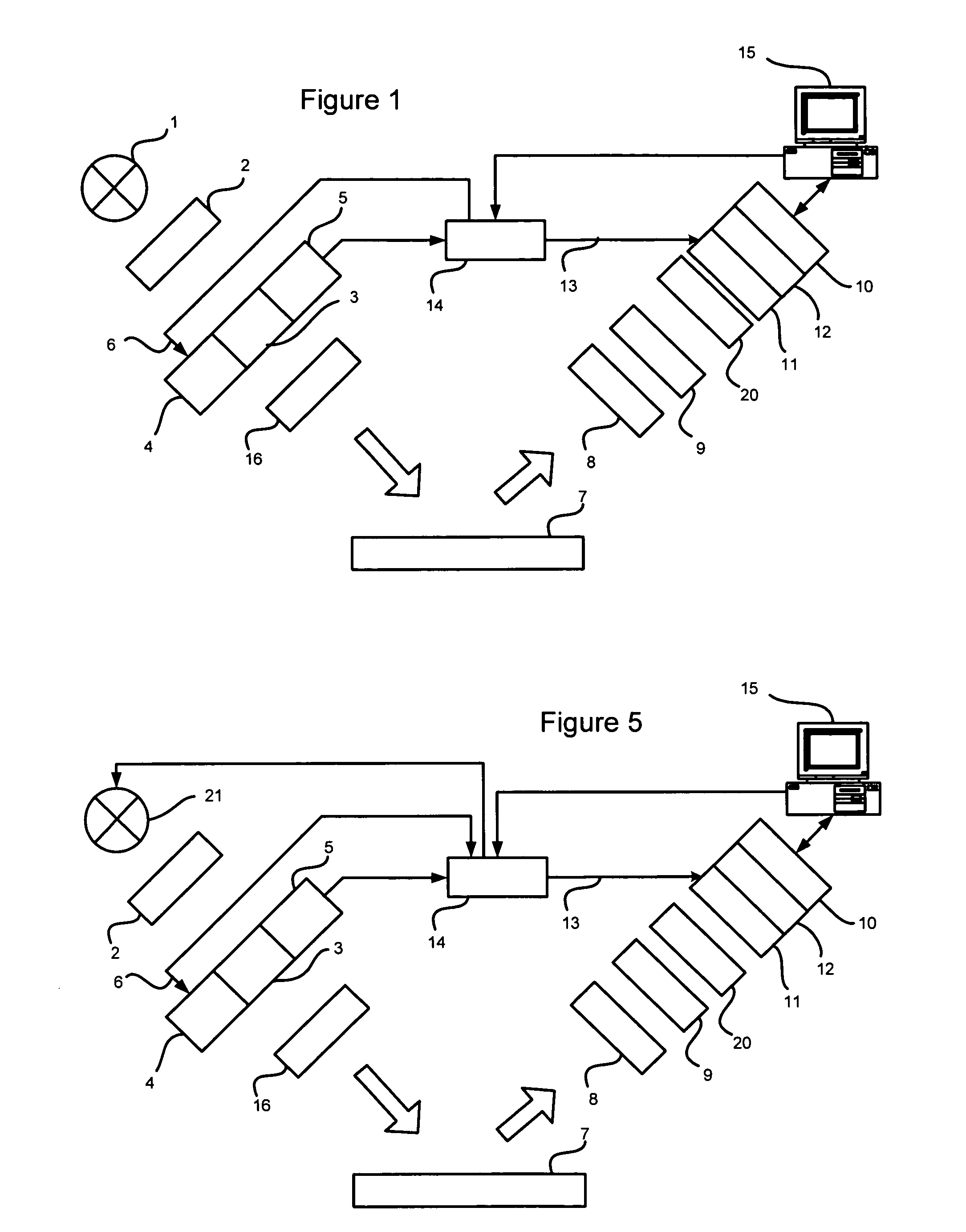
[0058] Various embodiments of the invention will now be described with reference to a first hardware example (FIG. 1) and a second hardware example (FIG. 5).

1 First Hardware Example: Modulator-Coherent Detector Signal Integrating Over Gated Intervals of a Modulator Cycle

1.1 Hardware

[0059]FIG. 1 shows a spectroscopic ellipsometer. Light from a white light source 1 passes through a polarizer 2, forming a beam of plane-polarized light. The polarized beam is modulated by a photoelastic birefringence modulator which comprises a fused silica modulator portion 3 which is driven into resonance by a piezoelectric drive element 4. A piezoelectric gauge element 5 generates a signal in response to the vibration of the modulator portion, and feeds the signal back into the drive element via a feedback path 6. An example of a suitable modulator is the High Stability Birefringence Modulator manufactured by Beaglehole Instruments Limited of 32 Salamanca Road, Wellington, New Zealand.

[0060] The...


PUM

PropertyMeasurementUnit
modulation frequency ωoaaaaaaaaaa
timeaaaaaaaaaa
energyaaaaaaaaaa

Abstract

The invention relates to a method of performing an optical measurement on a sample, such as an ellipticity measurement. The sample is irradiated with a polarized irradiation beam and a return beam is linearly polarized. The irradiation or return beam is modulated with a birefringence modulator, such as a photoelastic modulator, in accordance with a primary modulation signal. The return beam is directed onto a multichannel detector. Typically the detector is a slow detector, such as a CCD, having a response time greater than a period of the primary modulation signal. Detection values are generated simultaneously at each detection element and processed to determine a plurality of measurements. Various measurement techniques are described, including detector signal averaging over gated intervals; a design employing coherent modulation of the gain of an ICCD , and a modulator-coherent flash lamp design.

Description

[0001] This is a Continuation in Part of International Application No. PCT / NZ2004 / 0000010 filed Jan. 29, 2004 the contents of which are hereby incorporated herein by reference.FIELD OF THE INVENTION [0002] The invention relates to a method of performing an optical measurement on a sample, such as an ellipticity measurement. BACKGROUND OF THE INVENTION [0003] Ellipsometers have been used for a number of years in measurements of thin films. In particular, ellipsometers have been used in the measurement of oxide and other layers on semiconductors. Ellipsometers analyse the ellipticity induced by reflection from a surface, measuring two parameters. This technique enables much more precise measurements than are possible using reflectometry measurements, for example. [0004] A simple ellipsometer includes a light source which produces a beam of light which passes through a polarizer, forming a beam of light which is plane—polarised or has another well-defined polarisation state. The light ...

Claims


Application Information

Patent Timeline
Patent Type & Authority Applications(United States)
IPC IPC(8): G01J4/00G01N21/21
CPCG01N21/211
Inventor BEAGLEHOLE, DAVID
Owner ONTO INNOVATION INC
Why Eureka
Try Eureka