
Monitoring fuel cells using RFID devices

a technology of radio frequency identification and fuel cell, which is applied in the direction of fuel cells, fuel cell auxiliaries, electrochemical generators, etc., can solve the problems of internal damage to reversed cells and stacks, difficult to develop a suitable cell voltage monitor (cvm) for this purpose, and complex operation of a complete fuel cell system

Undetermined Publication Date: 2005-06-23
BALLARD POWER SYSTEMS
View PDF4 Cites 35 Cited by
  • Summary
  • Abstract
  • Description
  • Claims
  • Application Information

AI Technical Summary

Benefits of technology

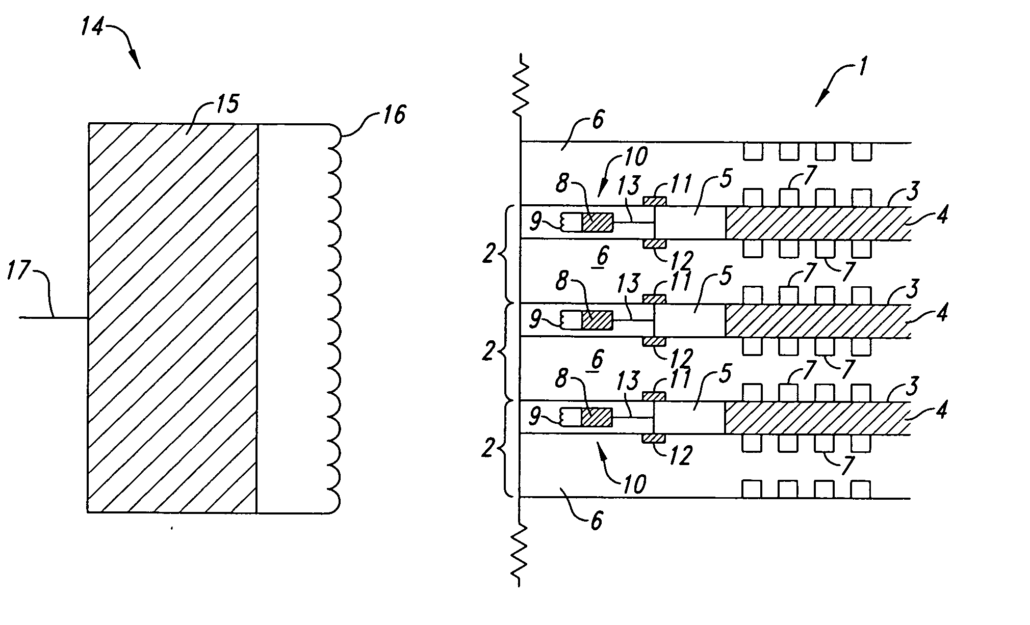
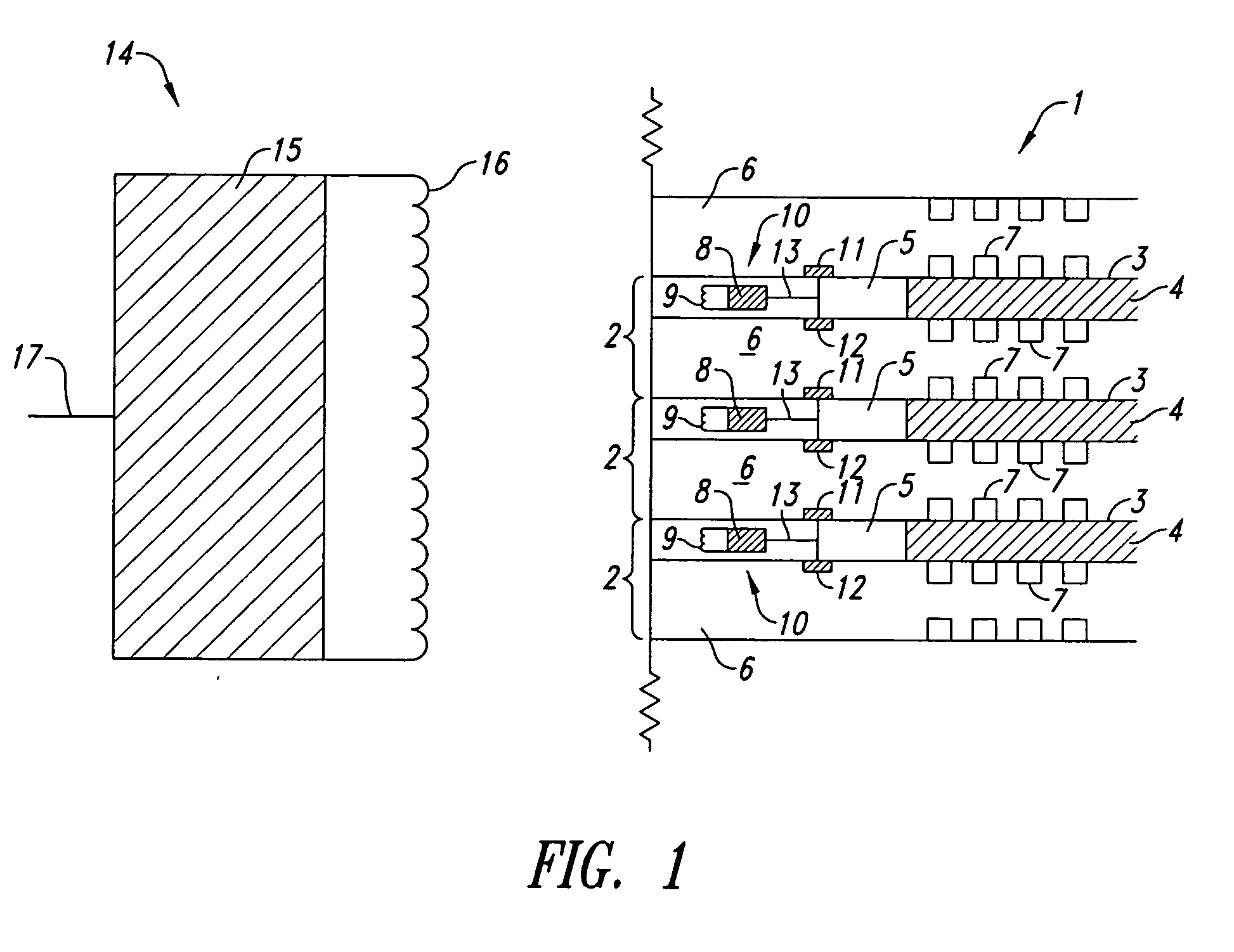
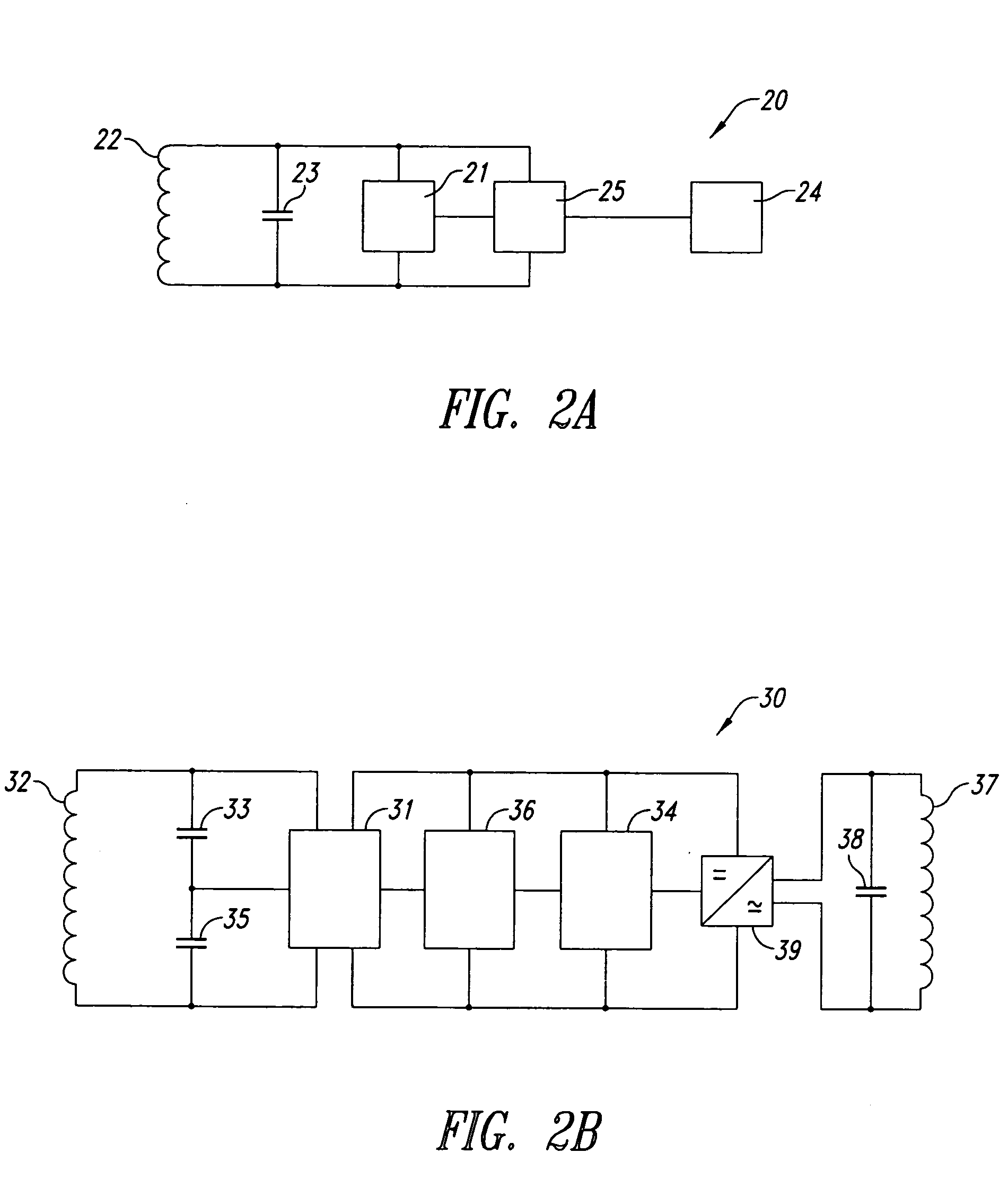
The patent describes a system for monitoring various operating parameters in fuel cells using RFID devices. These RFID transponder devices are placed in each fuel cell and are configured to sense and transmit information about the voltage of individual cells in a fuel cell stack. The transponder can also monitor other parameters such as cell impedance, temperature, reactant pressure, flow rate, and impurity concentration. The transponder is powered by an RFID reader and can be actively or passively powered. The system can prevent voltage reversal in the fuel cells by monitoring the cell voltage and alerting the reader when the voltage falls below a certain threshold value. Overall, the system provides an improved way to monitor and control fuel cell performance.

Problems solved by technology

The practical operation of a complete fuel cell system can thus be quite complex and various process or operating parameters may need to be monitored to provide feedback for satisfactory control and / or to provide a warning in the event of an impending problem condition.
Aside from being associated with a reduction in output power, voltage reversal also can result in internal damage to the reversed cells and the stack.
However, it has proven difficult to develop a suitable cell voltage monitor (CVM) for this purpose.
Problems have been encountered though with the electrical connections made to the cells and with the circuitry that generates the electrically isolated signals representative of the cell voltages.
With regards to making electrical connections to the cells, the assembly required is very labour intensive and it is becoming more difficult to align and install contacts as the designs of fuel cells advance and as the separator plates become progressively thinner and more closely spaced.
Further still, the fuel cell stack may be subject to vibration and thus reliable connections must be able to maintain contact even when subjected to vibration.
However, in the immediate vicinity of the stack, the environment may be humid, hot, and either acidic or alkaline.
Consequently, any metallic hardware in the immediate vicinity of the stack may be subject to corrosion and failure.
In particular, conductive traces that separate large voltages (e.g., in printed circuit board based isolation circuitry) are subject to corrosion and bridging via dendrite formation.
Still, it is not trivial to provide a satisfactory comprehensive, durable protective coating in this way.

Method used


Image

  • Monitoring fuel cells using RFID devices
  • Monitoring fuel cells using RFID devices
  • Monitoring fuel cells using RFID devices

Examples


example

[0048] A cell voltage monitoring system was designed for use in a solid polymer electrolyte fuel cell stack. The transponder design was similar to that generally shown in FIG. 2a and used commercially available RFID components, including a microID MCRF200 tag comprising a 125 kHz chip programmed in-house and a microID Reader. (These components are part of a microID Developer's kit that can be obtained from Microchip.) FIG. 4 shows a model of the operating transponder. In the model circuit of FIG. 4, chip 60 represents the aforementioned 125 kHz chip and coil 61 is a conventional coil provided with the kit. Resistor 62 and capacitor 63 represent the resistance and capacitance found in the modeled circuit and signal 64 represents the voltage induced in the circuit via interaction with the reader. The conventional circuit was modified by providing cathode and anode voltage inputs from simulated cell 65 at points 71 and 72, respectively, and transistor 68 and capacitor 69 were added to ...


PUM

PropertyMeasurementUnit
output voltageaaaaaaaaaa
frequencyaaaaaaaaaa
temperatureaaaaaaaaaa

Abstract

Radio frequency identification (RFID) devices may be used to monitor various operating parameters in fuel cells. For example, RFID devices may be used to monitor the voltage of individual cells in a fuel cell stack and thus to check for voltage reversal conditions during stack operation.

Description

BACKGROUND OF THE INVENTION [0001] 1. Field of the Invention [0002] The present invention relates generally to uses of radio frequency identification (RFID) devices in fuel cells, and, more particularly, to monitoring cell voltages and other operating parameters in solid polymer electrolyte fuel cell stacks. [0003] 2. Description of the Related Art [0004] Electrochemical fuel cells convert fuel and oxidant to generate electrical power and reaction products. A representative type of fuel cell is the solid polymer electrolyte fuel cell which employs a solid polymer, ion exchange membrane electrolyte. The membrane electrolyte is generally disposed between two electrode layers (a cathode and an anode layer) to form a membrane electrode assembly (MEA). In a typical solid polymer electrolyte fuel cell, the MEA is disposed between two electrically conductive separator or fluid flow field plates. Fluid flow field plates have at least one flow passage formed therein to direct a fluid reactan...

Claims


Application Information

Patent Timeline
Patent Type & Authority Applications(United States)
IPC IPC(8): H01M8/00H01M8/04H01M8/10
CPCH01M8/0432H01M8/04388H01M8/04395H01M8/04402H01M8/04432H01M8/04447Y02E60/50H01M8/04462H01M8/0447H01M8/04552H01M8/04641H01M8/04992H01M2008/1095H01M8/04455
Inventor KNAGGS, LESLIE BRENONORDUBADI, FARIBORZ T.VINK, EDWIN J.
Owner BALLARD POWER SYSTEMS
Learn More