Exhaust pressure-raising device for an internal combustion engine
a technology for exhaust pressure raising and internal combustion engines, which is applied in the direction of valve operating means/releasing devices, machines/engines, transportation and packaging, etc., can solve the problems of reducing the efficiency of fuel consumption, deteriorating combustion quality, and high cost, and achieves the improvement of exhaust emission quality and combustion stability or fuel consumption efficiency, simple construction, and low cost
- Summary
- Abstract
- Description
- Claims
- Application Information
AI Technical Summary
Benefits of technology
Problems solved by technology
Method used
Image
Examples
first embodiment
[0028] Firstly, a first embodiment will be explained.
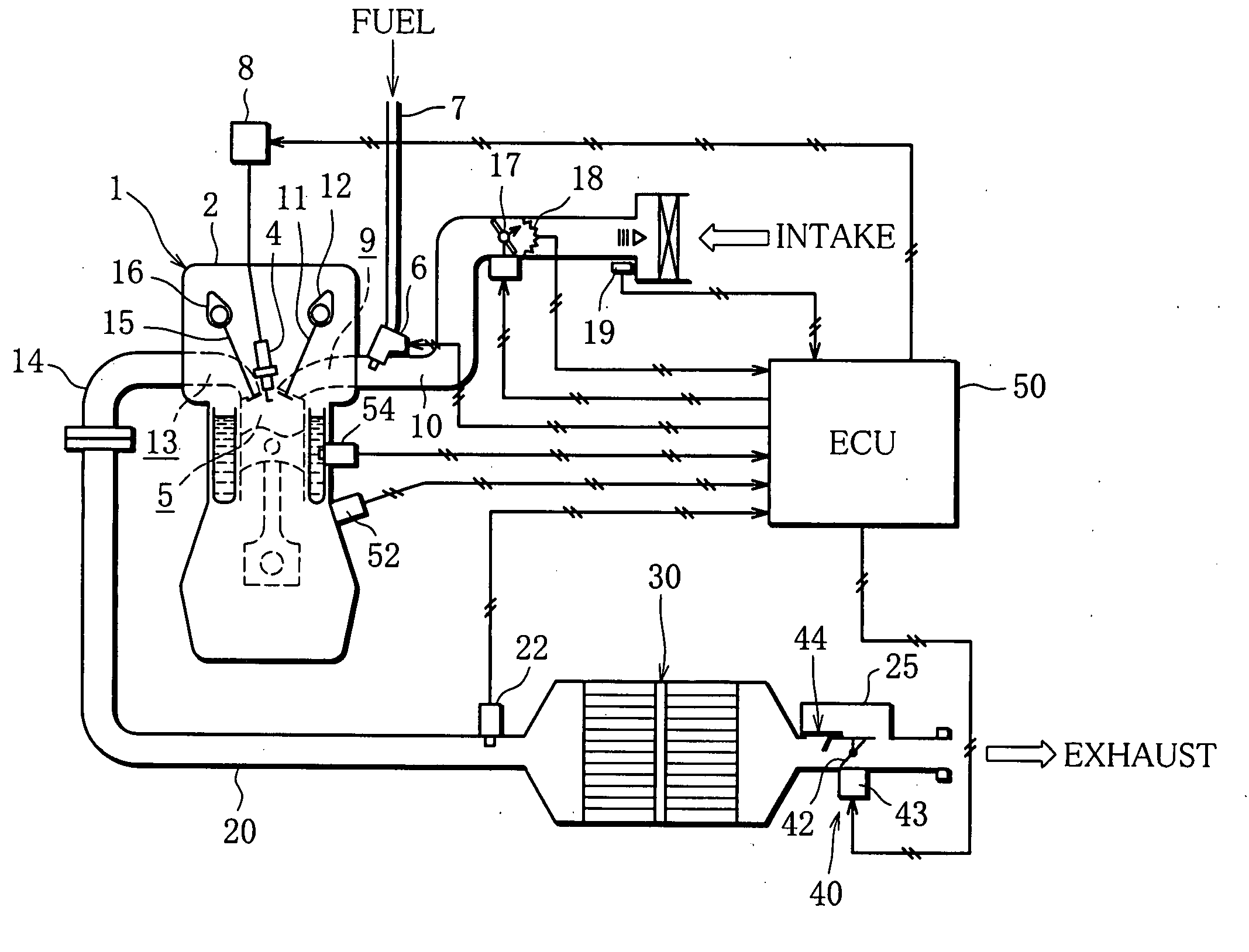
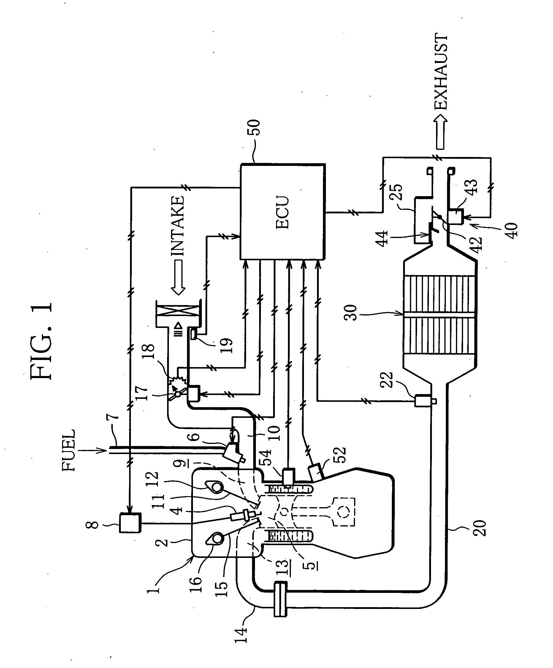
[0029]FIG. 1 schematically shows a system construction of an internal combustion engine including an exhaust pressure-raising device according to the present invention, which is installed in a vehicle.
[0030] As illustrated in FIG. 1, an intake-manifold injection (multipoint injection: MPI) type gasoline engine is employed as an engine body (hereinafter referred to as engine) 1 functioning as an internal combustion engine.
[0031] In a cylinder head 2 of the engine 1, an ignition plug 4 is attached to each cylinder, and an ignition coil 8 for outputting high voltage is connected to the ignition plug 4.
[0032] In the cylinder head 2, an intake port 9 is provided to each cylinder. An intake valve 11 is formed in each intake port 9 at an end close to a combustion chamber 5, the intake valve 11 being operated to open and close along with a cam of a cam shaft 12 that rotates according to engine revolution and makes the intake port 9 com...
second embodiment
[0063] Next, a second embodiment will be explained below.
[0064] A difference between the second embodiment and the first, in terms of the exhaust pressure-adjusting valve 44, is the attaching position of the shield. Hereinafter, the explanation about the parts identical to those of the first embodiment will be omitted, and the parts different from those of the first embodiment will be described.
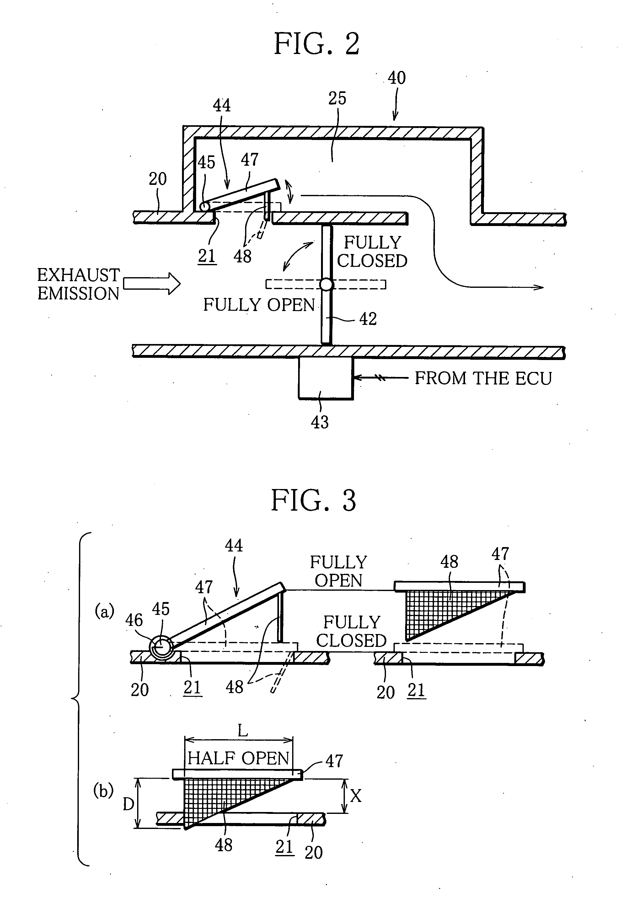
[0065]FIG. 5 is a detail view of an exhaust pressure-adjusting valve 44′ according to the second embodiment, showing a fully open position (a) and a half-open position (b). The details about the exhaust pressure-adjusting valve 44′ according to the second embodiment will be described below with reference to FIG. 5.
[0066] As illustrated in FIG. 5, in the exhaust pressure-adjusting valve 44′, a shield 48′ is disposed upright not in the end of the valve element 47 but in the outer circumferential surface of the exhaust pipe 20 to be positioned downstream of the exhaust flow from the opening ho...
third embodiment
[0070] Next, a third embodiment will be described below.
[0071] The third embodiment is different in that the shield 48′ of the exhaust pressure-adjusting valve 44′ of the second embodiment is improved. The explanation about the parts identical to those of the first and second embodiments will be omitted, and only the parts different from those of the second embodiment will be described.
[0072]FIG. 6 is a detail view of an exhaust pressure-adjusting valve 44′ according to the third embodiment, showing a fully open position (a) and a half-open position (b). Hereinafter, the detail about the exhaust pressure-adjusting valve 44′ according to the third embodiment will be explained with reference to FIG. 6.
[0073] As illustrated in FIG. 6, in the exhaust pressure-adjusting valve 44′, a shield 48″ is disposed upright in the outer circumferential surface of the exhaust pipe 20 to be positioned downstream of the exhaust flow from the opening hole 21 to sit at the circumferential edge of the ...
PUM
 Abstract
Description
Claims
Application Information
 - R&D
- Intellectual Property
- Life Sciences
- Materials
- Tech Scout
- Unparalleled Data Quality
- Higher Quality Content
- 60% Fewer Hallucinations
Browse by: Latest US Patents, China's latest patents, Technical Efficacy Thesaurus, Application Domain, Technology Topic, Popular Technical Reports.
© 2025 PatSnap. All rights reserved.Legal|Privacy policy|Modern Slavery Act Transparency Statement|Sitemap|About US| Contact US: help@patsnap.com


