Method and apparatus for measuring velocity of chromatagraphic pulse

a chromatographic pulse and velocity measurement technology, applied in the field of gas chromatography, can solve the problems of single-stage modulators, ohmic coatings to burn out, and suffer certain limitations, and achieve the effects of high quality, low cost, and convenient us

Inactive Publication Date: 2005-06-30
ZOEX
View PDF7 Cites 18 Cited by
  • Summary
  • Abstract
  • Description
  • Claims
  • Application Information

AI Technical Summary

Benefits of technology

[0025] It is an object of the present invention to provide a capillary column holder that is robust in its construction, and easy to use.
[0027] It is an object of the present invention to provide a means for multi-stage thermal modulation that is sufficiently inexpensive, manufacturable, and easy to use, as to be a commercially viable product in the field of gas chromatography.

Problems solved by technology

Single stage modulators, such as those described in the above publications, were found to concentrate and release sample substances as sharp chemical pulses, but suffered certain limitations.
Overdriving caused ohmic coatings to burn out at unpredictable. times. A further limitation of the above designs was undesirable tailing of the concentration pulses generated, which limited the utility of the devices for sampling continuous, or semi-continuous sample streams, such as the effluent of an analytical GC column.
As originally implemented, however, ohmically heated two-stage thermal modulators burned out frequently, and unpredictably, and were moreover difficult to prepare and handle.
Although their heater system was reliable, their implementation employed moving parts in the vicinity of the column, which made the device difficult to manufacture and handle in the field.
The principle drawback of this design was the complexity of the apparatus, which employed four valves, a heat exchanger, and a bulky mechanical assembly for positioning a modulator tube in the paths of pulsed hot and cold jets.
Even with the admirable simplicity and good performance of the Beens design, certain limitations were encountered.
First, liquid carbon dioxide refrigerant employed in the cold jets produces jet gas temperatures of about −77° C., unsuitable for modulation of chemical compounds with volatilities greater than that of octane.
This is problematical for important samples such as gasoline and naptha, in which modulation over the C5+ range, or lower carbon numbers, is desirable.
Second, the carbon dioxide consumption rate of the jets was high enough (c.a.
Third, dead volume between the valves and the jet nozzles could be cleared rapidly only at high gas flow rates.
At low gas flow rates, it would be questionable whether the dead volumes would clear rapidly enough to permit high quality thermal modulation.
Thus the Beens device requires fairly high gas flow rates through the cold jets.
Fourth, high pressure valves present risks to operators that low-pressure valves do not, and are moreover expensive.
Seventh, permanent frost spots appeared on the capillary columns when the cold jets were pulsed at high frequencies, indicating that the heating rate provided by an ambient oven limits the frequency at which the modulator could operate.

Method used


Image

  • Method and apparatus for measuring velocity of chromatagraphic pulse
  • Method and apparatus for measuring velocity of chromatagraphic pulse
  • Method and apparatus for measuring velocity of chromatagraphic pulse

Examples


Embodiment Construction

[0042] The present invention can be further described in terms of the following methods and apparatus:

[0043] A method, herein referred to as method “A,” comprises a method of thermal modulation for generating chemical pulses in a fluid stream flowing through a modulator tube, said method comprising the steps of: [0044] a. providing a modulator tube comprising an inlet, a first portion in communication with said inlet, a second portion in communication with said first portion, and an outlet portion in communication with said second portion; [0045] b. creating a fluid stream in a direction through the modulator tube to produce a carrier fluid stream; [0046] c. introducing a sample into the carrier fluid stream, said sample comprising one or more chemical substances; [0047] d. manipulating the temperature of the first portion to cause at least a portion of the sample to be retained therein; [0048] e. manipulating the temperature of the second portion such that at least a portion of th...


PUM

PropertyMeasurementUnit
temperaturesaaaaaaaaaa
temperatureaaaaaaaaaa
temperaturesaaaaaaaaaa

Abstract

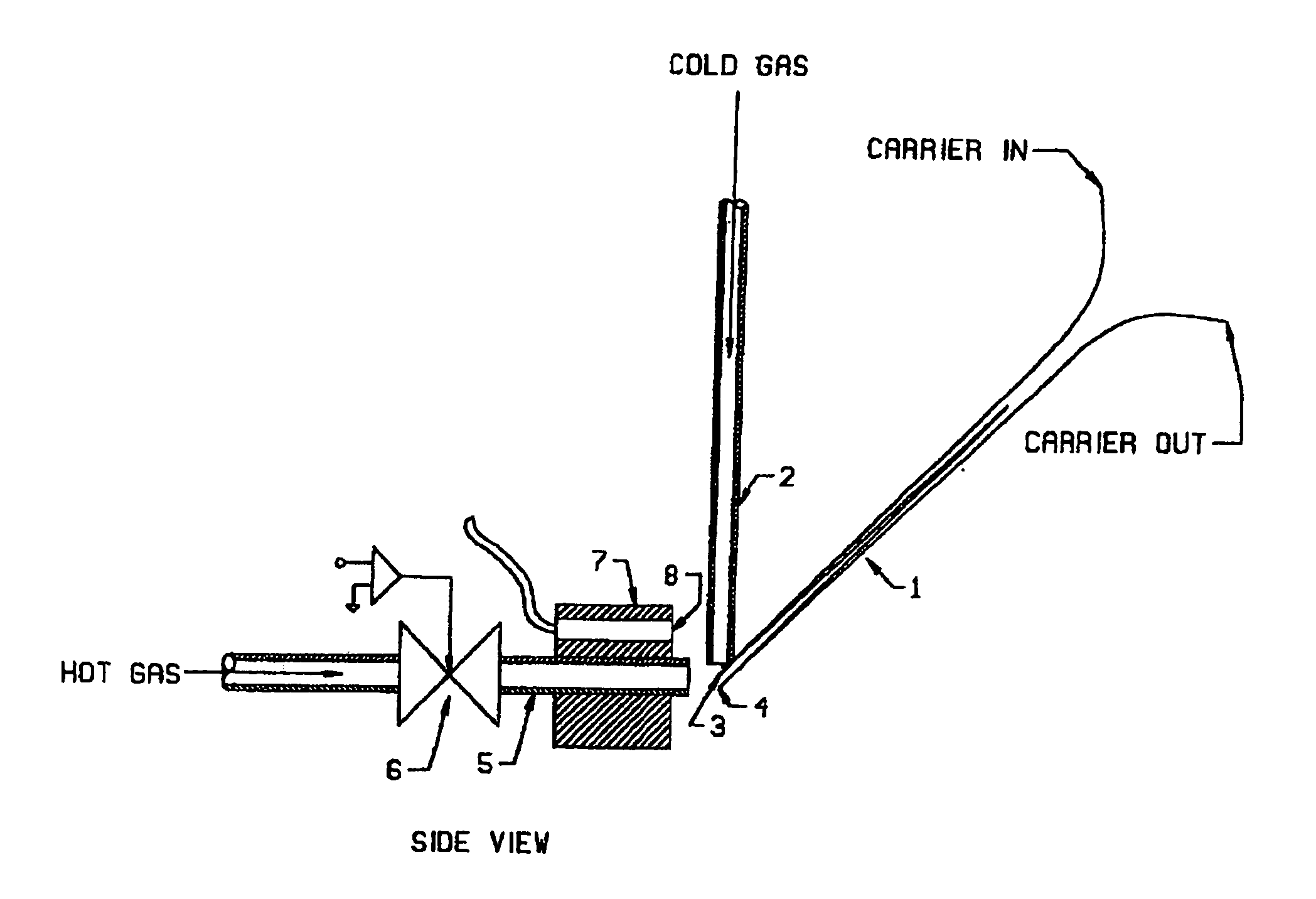
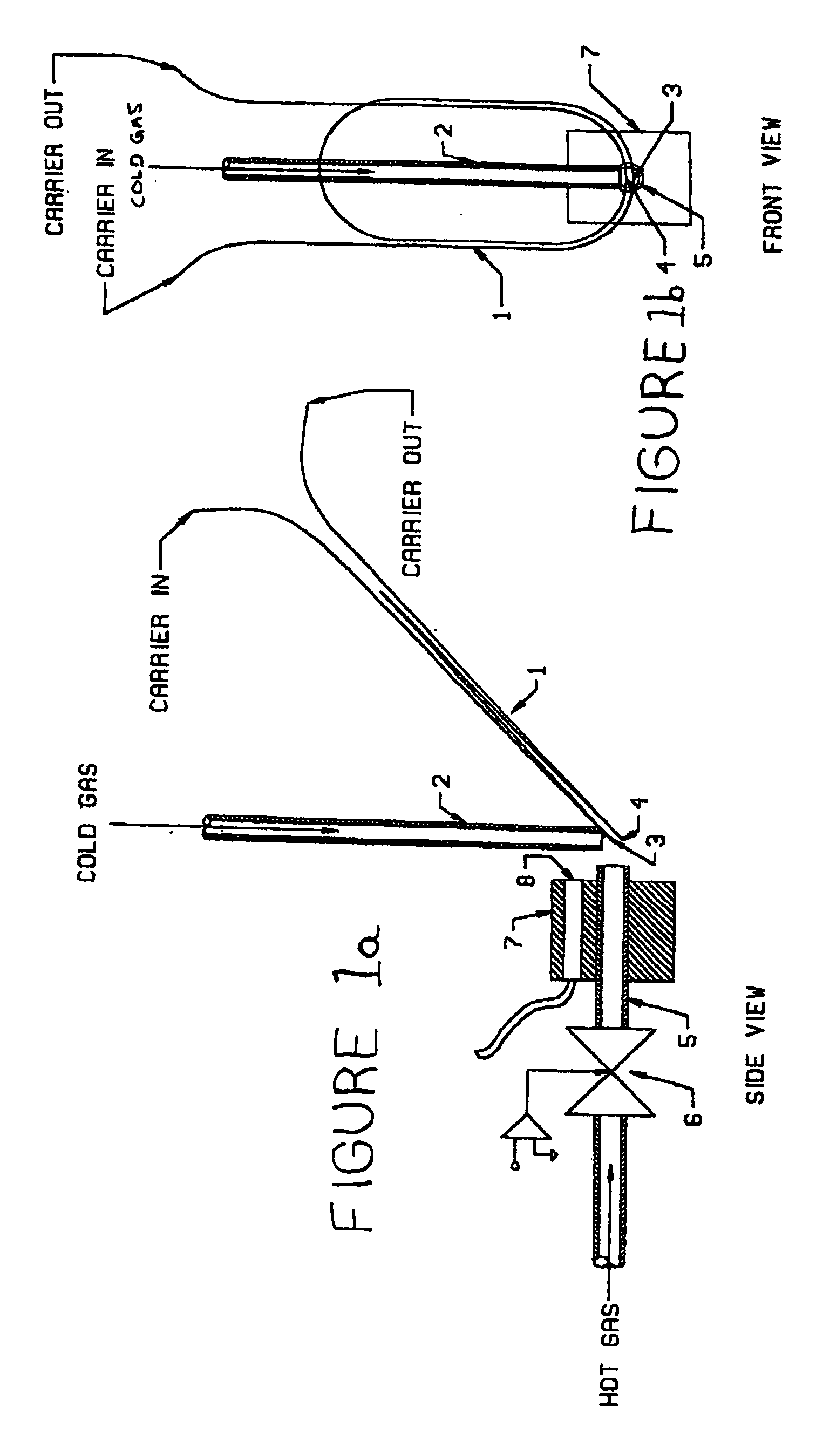
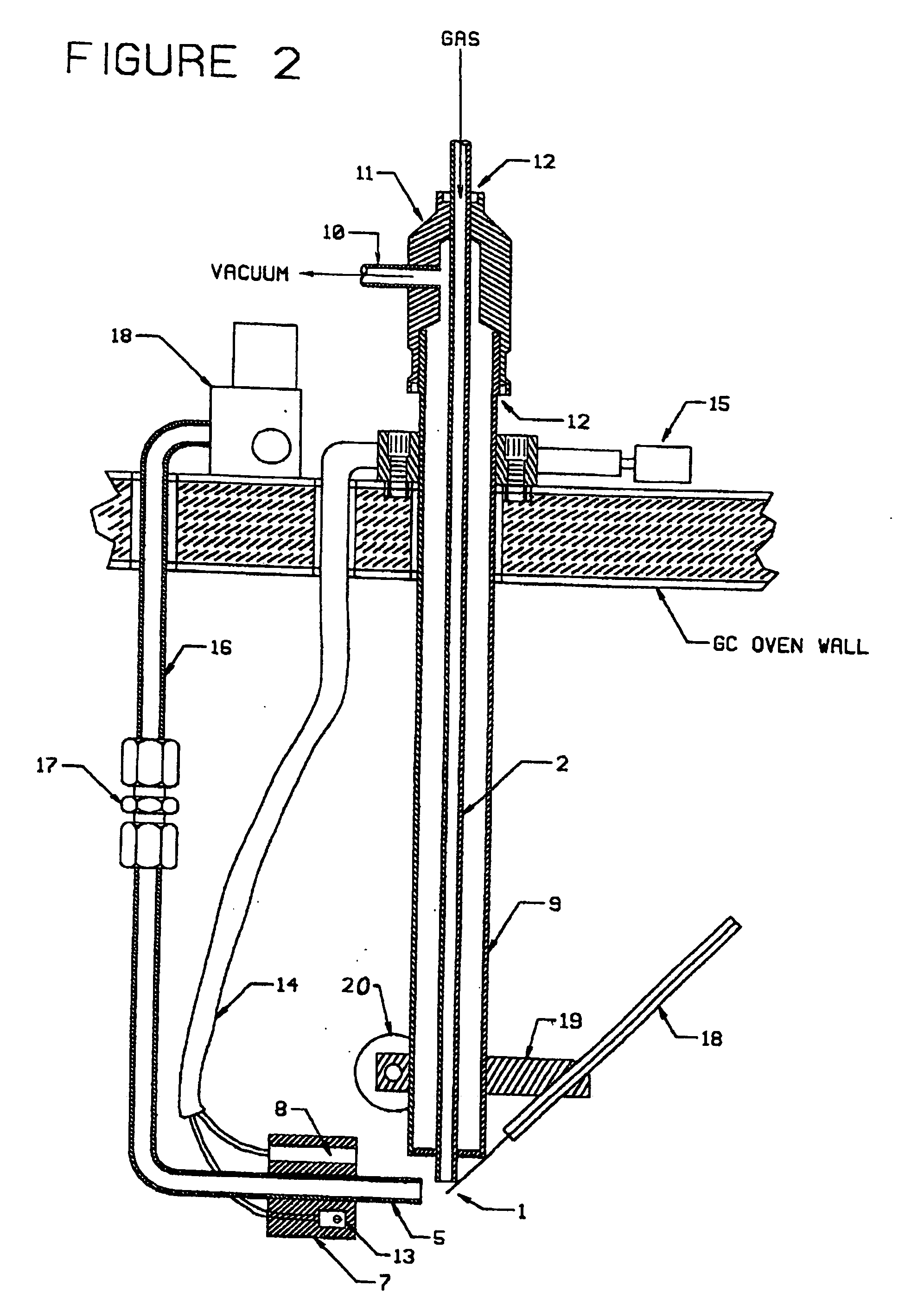
An Apparatus and method for two-stage chromatographic separation uses thermal modulation. The chromatographic column or modulation tube (1) has a loop structure such that two portions of modulation tube (1) can be thermally modulated simultaneously by at least one thermal modulation device, which device can have a cold gas source, jet tube (2), and a hot gas source, hot jet tube (5), to modulate the temperature of the portions (3, 4) of modulation tube (1).

Description

FIELD OF THE INVENTION [0001] This invention relates to the field of gas chromatography. BACKGROUND OF THE INVENTION PRIOR ART THERMAL MODULATION [0002] Thermal modulation is a means of producing chemical pulses of short duration in capillary gas chromatographic columns. [0003] Thermal modulators grew out of prior art ohmically heated cryogenic traps, which received attention in the scientific literature for some years, following demonstration by Hopkins and Pretorious that ohmic heating of cryogenic traps was faster than the heating obtained with a hot gas stream. (B. J. Hopkins, and V. Pretorious, Journal of Chromatography, 158 (1978) 471). A number of ohmically heated single stage thermal modulators were reported, examples of which are described in the following publications, incorporated in their entireties herein by reference: [0004] 1. J. Phillips, et al. “Thermal Desorption Modulation as a Replacement for Sample Injection in Very-Small-Diameter Gas Chromatography Capillary Co...

Claims


Application Information

Patent Timeline
Patent Type & Authority Applications(United States)
IPC IPC(8): G01N30/30B01D15/08G01N30/02G01N30/16G01N30/32G01N30/46G01N30/62
CPCG01N30/463G01N30/465G01N2030/025G01N2030/623G01N2030/3023G01N2030/324G01N2030/123
Inventor LEDFORD JR, EDWARD B.
Owner ZOEX
Why Eureka
Try Eureka