Disposition structure of heat exchanger in motorcycle

a technology of heat exchanger and disposition structure, which is applied in the direction of cycle equipment, machines/engines, cycles, etc., can solve the problems of inability to achieve maximum efficiency of heat exchanger, inability to achieve high cooling effect, and large exchanger size, so as to improve cooling properties, increase cooling efficiency, and increase air flow

Inactive Publication Date: 2005-06-30
HONDA MOTOR CO LTD
View PDF8 Cites 11 Cited by
  • Summary
  • Abstract
  • Description
  • Claims
  • Application Information

AI Technical Summary

Benefits of technology

[0022] Therefore, by installing at an angle of the best efficiency with respect to a flow of the air flow of the motorcycle, it is possible to apply more air flow to the cooling fins of the heat exchanger for raising the cooling efficiency, and since an advance-guard projected area of the heat exchanger as viewed from the front of the vehicle can be reduced, a flow rate of the air flow to be conducted into the engine itself also increases, and it is possible to conduct the air flow to each of the heat exchanger and the engine. As a whole, the cooling property can be improved.
[0023] According to a second aspect of the present invention, since the heat exchanger has been provided in the upper part of a crankcase in the neighborhood below a cylinder of the internal combustion engine, an air flow that has changed its direction by striking against the cylinder and the cylinder head can be effectively introduced into the heat exchanger and be utilized.
[0024] According to a third aspect of the present invention, since a pitch of the cooling fins in the heat exchanger has been made larger in the central part, and smaller in the end portions, by widening the pitch in the central part of the heat exchanger, it is possible to restrain the air flow from being spread by the heat exchanger, and as a result, a lot of air flow can be caused to pass through the heat exchanger. Also, in the case of the air-cooled internal combustion engine, the air flow that has struck against the heat exchanger can be effectively introduced to the cooling fins and the like provided on the cylinder.
[0025] According to a fourth aspect of the present invention, since the heat exchanger has been formed in a round shape, the air flow that is going through sideways from the heat exchanger can be effectively used for cooling.
[0026] According to a fifth aspect of the present invention, since a cylinder block above the heat exchanger has been provided with cooling fins in a direction of the cylinder axis, the cylinder block is positively utilized as a wall against the air flow, whereby utilization efficiency of the air flow can be improved. In other words, the air flow that has struck against the cylinder block can be positively introduced toward the heat exchanger by the cooling fans directed toward the direction of the cylinder axis.

Problems solved by technology

Hei 1-176591), in such a disposition structure of the heat exchanger, an angle of incidence of the air flow to cooling fins of the heat exchanger becomes small so that no high cooling effect can be obtained.
As a result, the maximum efficiency in the heat exchanger could not be brought about; however in order to secure sufficient cooling property in the internal combustion engine, it was necessary to make the heat exchanger larger sized.
In the case of an air-cooled internal combustion engine, when there is the heat exchanger in front of the internal combustion engine, an air flow rate to be applied to the engine decreases, and when the heat exchanger is large, a problem in design cannot be ignored either.
Since, however, the air flow flows away so as to stroke the surface of the cooling fins, the formation of a smooth flow in the air flow is not capable of applying a sufficient amount of air flow to the cooling fins, nor is sufficient cold given to the fin surface of the cooling fins, and in the sense that the cold of the air flow is more effectively absorbed to make the best use in the cooling fins, any acceptable result is never given.
Also, according to the above-described disposition structure of heat exchanger, since a plane having large area on which a multiplicity of cooling fins of the heat exchanger stand in a row opposes an air flow so as to intercept at right angles or substantially at right angles, its projected area is large, and a flow of the air flow to be directly applied to the engine is significantly affected leading to the decreased running air flow rate to be directly applied to the engine.
Therefore, the above-described disposition structure of heat exchanger is not appreciated from a point of view of cooling of the engine in above all air-cooled internal combustion engine.

Method used


Image

  • Disposition structure of heat exchanger in motorcycle
  • Disposition structure of heat exchanger in motorcycle
  • Disposition structure of heat exchanger in motorcycle

Examples


first embodiment

[0044] the present invention will be described with reference to FIGS. 1 to 12.

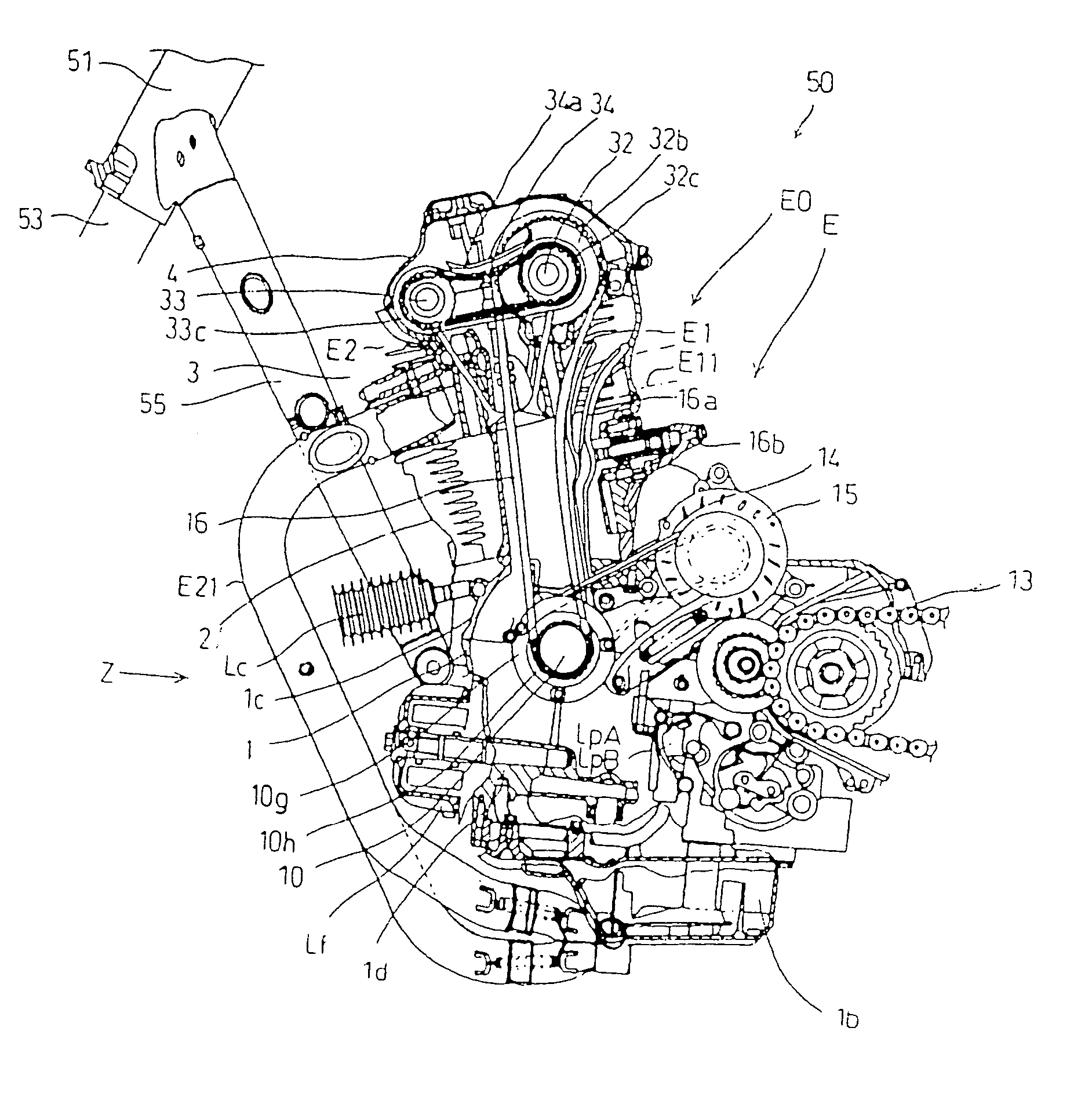
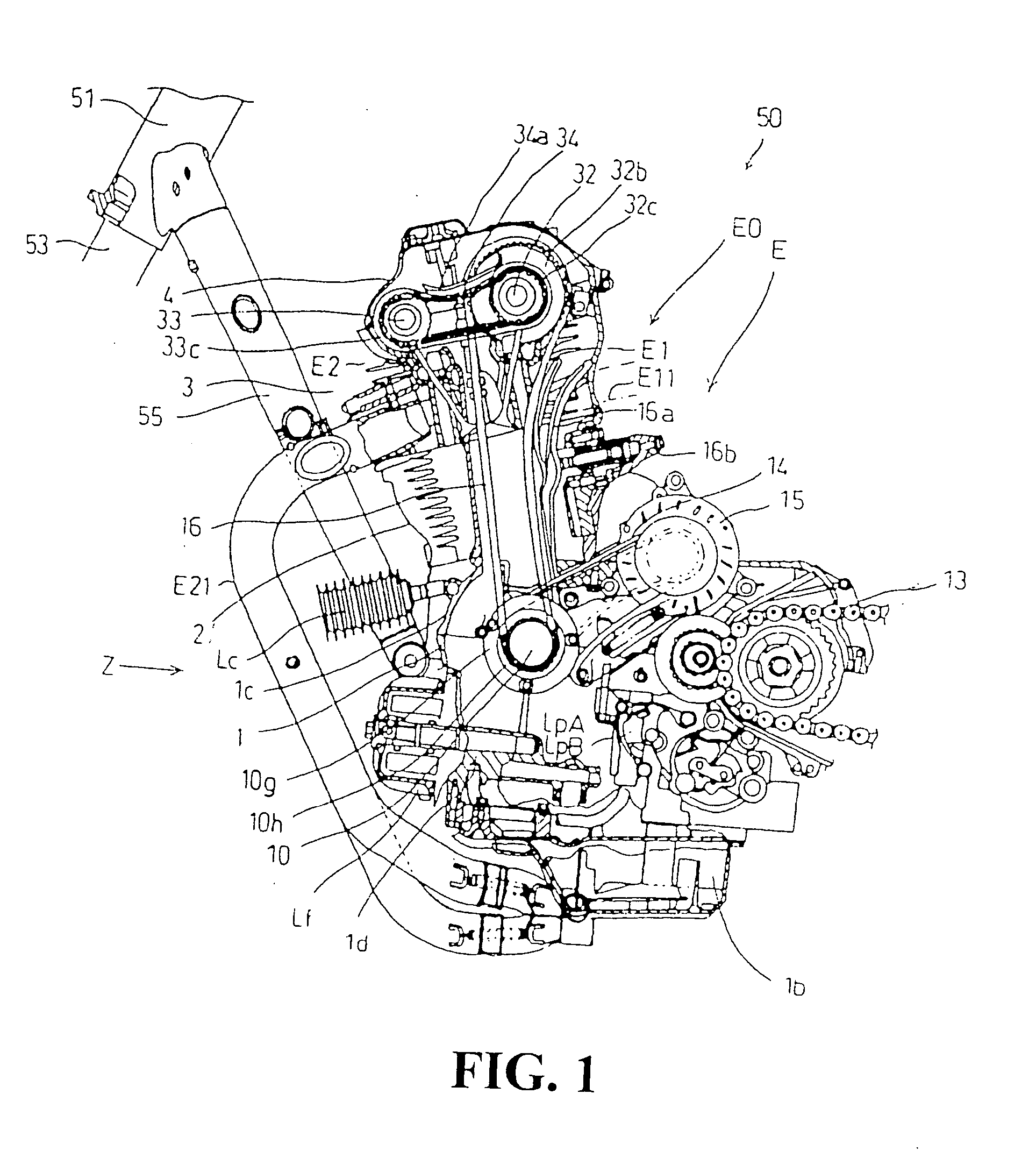
[0045]FIG. 1 shows partial structure of a motorcycle, which is a vehicle 50 on which an internal combustion engine E equipped with a heat exchanger according to the first embodiment is to be mounted, and in the figure concerned, only the structure in the neighborhood of a portion on which the engine E has been mounted is shown. The motorcycle has a head pipe 51 for forming a front part of its body frame, and the head pipe is provided with a front fork 53 (see FIG. 11) for supporting a front wheel 52 which is not shown in FIG. 1 in the lower part thereof, and a handlebar, not shown, mounted on the upper part thereof.

[0046] Main frame and down tube, not shown, are installed in the head pipe 51; seat rail and back stay, not shown, are installed in the main frame; and further a swing arm 58 for supporting a rear wheel is installed therein.

[0047] The body frame is mounted with an internal combustion engine E...


PUM


Abstract

A disposition structure of a heat exchanger (oil cooler) in a motorcycle mounted in the central part in front of the upper part of the crankcase of an internal combustion engine E mounted on the motorcycle. When viewed from the front of the motorcycle, the oil cooler is located between the front forks. The oil cooler is disposed so that the fin surface of the cooling fins of the heat exchanger are perpendicular or substantially perpendicular to an air flow that goes between the front forks and above the front wheel. In the disposition structure so configured, cooling efficiency of the heat exchanger is improved.

Description

CROSS-REFERENCE TO RELATED APPLICATION [0001] The present application claims priority under 35 U.S.C. §119 to Japanese Patent Application No. 2003-435632, filed Dec. 26, 2003, Japanese Patent Application No. 2004-181274, filed Jun. 18, 2004, the entire contents of which are hereby incorporated by reference. BACKGROUND OF THE INVENTION [0002] 1. Field of the Invention [0003] The present invention relates to a disposition structure of a heat exchanger in a motorcycle, and more particularly to improvement technique on a disposition structure of a heat exchanger on a motorcycle, which has been considered from a point of view of improving cooling efficiency of the heat exchanger. [0004] 2. Description of Background Art [0005] Conventionally, as disposition structure of the heat exchanger in a motorcycle, there is known structure in which a heat exchanger has been disposed forward of an internal combustion engine. Thus, this disposition structure of the heat exchanger is that it has been ...

Claims


Application Information

Patent Timeline
Patent Type & Authority Applications(United States)
IPC IPC(8): B62J31/00B60K11/04B62K11/04F01M5/00F01P3/18F02B61/02F02F1/06
CPCB62K11/04F02B61/02F01M5/002
Inventor GOKAN, YOSHITSUGUTAKAHASHI, YASUSHI
Owner HONDA MOTOR CO LTD
Why Eureka
Try Eureka