Onboard hydrogen storage unit with heat transfer system for use in a hydrogen powered vehicle

a hydrogen storage unit and heat transfer technology, applied in the direction of packaging goods, container discharging methods, separation processes, etc., can solve the problems of fossil fuel pollution, constant movement of the global energy system, and virtually unlimited supply of hydrogen

Inactive Publication Date: 2005-06-30
VODIK LABS LLC +1
View PDF3 Cites 10 Cited by
  • Summary
  • Abstract
  • Description
  • Claims
  • Application Information

AI Technical Summary

Benefits of technology

[0018] During refueling, the primary loop is an open loop. The primary loop receives a stream of cooling fluid from an outside source, such as the refueling station. The primary loop includes one or more tubes in thermal contact with said hydrogen storage alloy. The cooling fluid thereby circulates through the primary loop and removes any heat produced by the absorption of hydrogen into the hydrogen storage alloy.

Problems solved by technology

As the world's population expands and its economy increases, the atmospheric concentrations of carbon dioxide are warming the earth causing climate change.
However, the global energy system is moving steadily away from the carbon-rich fuels whose combustion produces the harmful gas.
Furthermore, fossil fuels cause pollution and are a causative factor in the strategic military struggles between nations.
As noted in recent newspaper articles, large industries, especially in America, have long been suspicious of claims that the globe is warming and have vociferously negated the science of climate change.
Hydrogen is the “ultimate fuel.” In fact, it is considered by most to be “THE” fuel for the next millennium, and, it is inexhaustible.
While the world's oil reserves are depletable, the supply of hydrogen remains virtually unlimited.
Furthermore, hydrogen, although presently more expensive than petroleum, is an inherently low cost fuel.
While hydrogen has wide potential application as a fuel, a major drawback in its utilization, especially in mobile uses such as the powering of vehicles, has been the lack of acceptable lightweight conmpact hydrogen storage medium.
Storage of hydrogen as a compressed gas or liquid involves the use of large and / or cryogenic vessels, making the use of hydrogen to power vehicles less feasible.

Method used


Image

  • Onboard hydrogen storage unit with heat transfer system for use in a hydrogen powered vehicle
  • Onboard hydrogen storage unit with heat transfer system for use in a hydrogen powered vehicle
  • Onboard hydrogen storage unit with heat transfer system for use in a hydrogen powered vehicle

Examples


Embodiment Construction

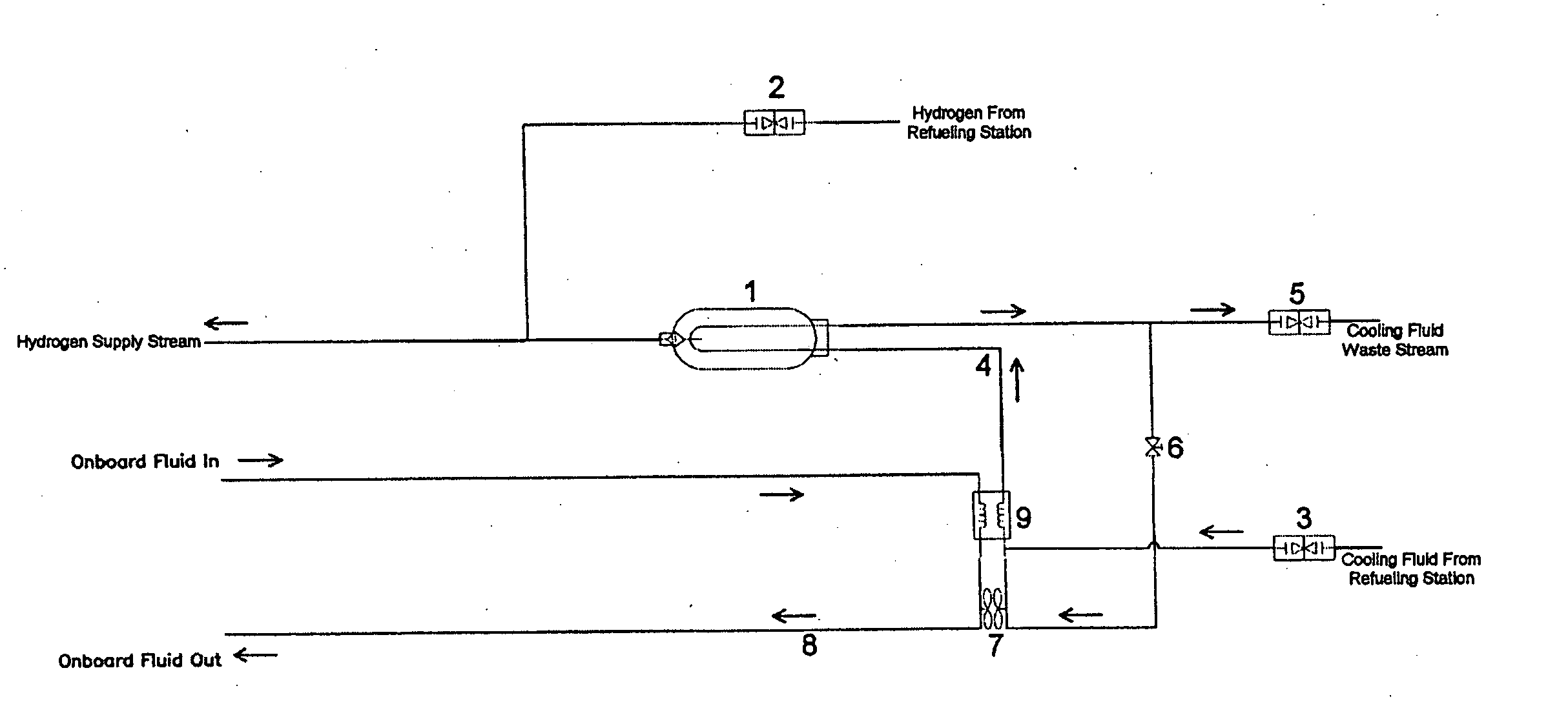
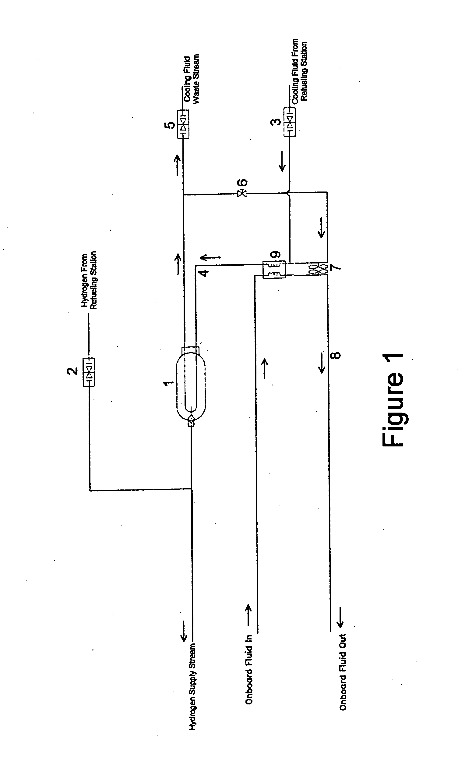
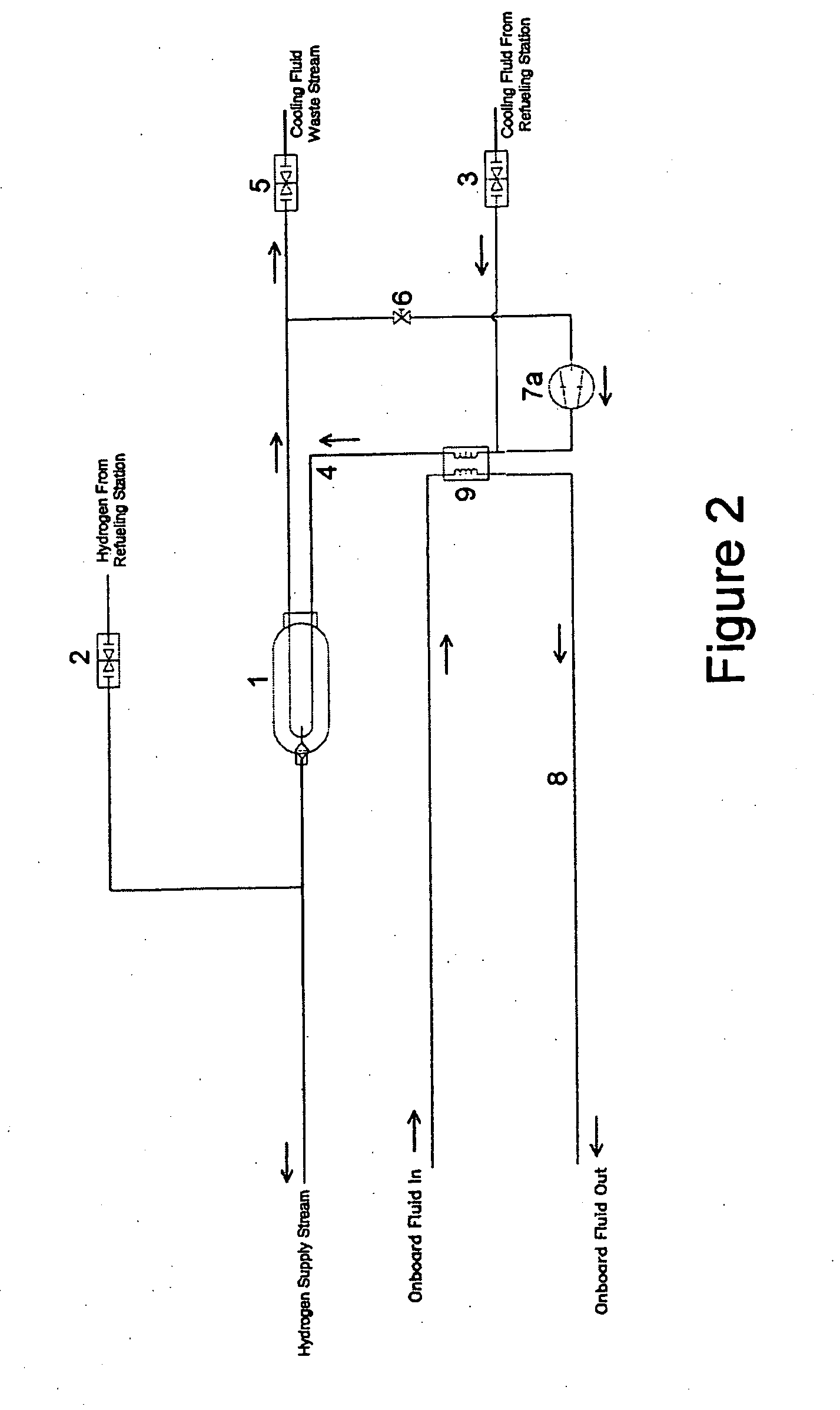
[0026] The present invention discloses an onboard hydrogen storage unit with heat transfer system for use in a hydrogen powered vehicle. The heat transfer system is designed to be used in conjunction with at least one hydrogen storage vessel at least partially filled with a hydrogen storage alloy. The hydrogen storage vessels are configured to receive hydrogen from a refueling station and supply the hydrogen as needed for fuel. The hydrogen may be used as fuel for a fuel cell, a hydrogen powered internal combustion engine, or other means for propelling a vehicle using hydrogen as a fuel.

[0027] During refueling, the hydrogen storage alloy contained inside the hydrogen storage vessel absorbs hydrogen, thereby producing a considerable amount of heat (heat of hydride formation). If the heat remains present, the rate of absorption of hydrogen into the hydrogen storage alloy is decreased and the time for refueling the vessel is increased. The heat created by the absorption of the hydroge...


PUM

PropertyMeasurementUnit
heat transferaaaaaaaaaa
concentrationsaaaaaaaaaa
of energyaaaaaaaaaa

Abstract

An onboard hydrogen storage unit with heat transfer system for a hydrogen powered vehicle. The system includes a hydrogen storage vessel containing a hydrogen storage alloy configured to receive a stream of hydrogen and provide hydrogen for use in powering a vehicle. During refueling a cooling / heating loop is used to remove the heat of hydride formation from the hydrogen storage alloy and during operation of the vehicle the heating / cooling loop is used to supply heat to the hydrogen storage alloy to aid in hydrogen desorption.

Description

CROSS REFERENCE TO RELATED APPLICATIONS [0001] The present invention is a continuation of, and is entitled to the benefit of the earlier filing date and priority of, co-pending U.S. patent application Ser. No. 10 / 218,941, entitled “Onboard Hydrogen Storage Unit With Heat Transfer System For Use In A Hydrogen Powered Vehicle”, filed Aug. 14, 2002, which is assigned to the same assignee as the current application, the disclosure of which is hereby incorporated by reference.FIELD OF THE INVENTION [0002] The present invention generally relates to cooling and heating systems for hydrogen storage units. More particularly, the present invention relates to a heat transfer system used to cool a hydrogen storage vessel utilizing a hydrogen storage alloy upon charging at a hydrogen fueling station and a heating system used to heat the hydrogen storage vessel to aid in release of hydrogen during cold startup and operating conditions. BACKGROUND [0003] As the world's population expands and its e...

Claims


Application Information

Patent Timeline
Patent Type & Authority Applications(United States)
IPC IPC(8): B01D53/02F17C11/00
CPCB01D53/02F17C6/00F17C9/00F17C11/005F17C2221/012Y02E60/321F17C2227/0355F17C2260/02F17C2265/065F17C2265/066F17C2270/0168F17C2227/0323C01B3/0005Y02E60/32
Inventor MYASNIKOV, VITALIYYOUNG, ROSALI, YANGOVSHINSKY, STANFOND R.
Owner VODIK LABS LLC
Why Eureka
Try Eureka