
Power generator and torque amplifier

a technology of torque amplifier and power generator, which is applied in the direction of machines/engines, magnetic circuit rotating parts, and shape/form/construction of magnetic circuits, etc., can solve the problems of poor practicality, risk of leakage of magnetic flux from ferromagnetic members, and so as to achieve efficient output power, reduce the effect of deterioration of magnetic force and large torque amplification coefficien

Inactive Publication Date: 2005-06-30
OGOSHI MAKOTO
View PDF6 Cites 25 Cited by
  • Summary
  • Abstract
  • Description
  • Claims
  • Application Information

AI Technical Summary

Benefits of technology

"The present invention provides a torque amplifier and a power generator with a simple structure and large torque amplification coefficient. The torque amplifier has a rotatable rotor with permanent magnets and coreless coils, and the power generator has a rotor with permanent magnets and magnet wheels. The generators can efficiently obtain an output power relative to an input power. The technical effects of the invention are improved performance and efficiency of power generation."

Problems solved by technology

While the aforementioned magnetic rotation apparatus can purportedly provide an output power greater than an input power, it has poor practicality because the difference between the output and input powers or a torque amplification coefficient is too small for an increased size of the apparatus caused by the need for intricately combining a member of permanent magnets.
Moreover, the magnetic rotation apparatus is not designed to generate electrical power from an electromagnet, and thereby a power generator has to be connected to a driven rotor of the magnetic rotation apparatus to generate electrical power.
This structure inevitably causes deterioration in magnetic force at the magnetic gaps for receiving the coil therein, and involves the risk of leakage of the magnetic flux from the ferromagnetic members if another magnetic member is located adjacent to the ferromagnetic members.
Moreover, the power generator utilizing a magnetic flux from a single rod-shaped magnet has limitations in amplifying an output power.

Method used


Image

  • Power generator and torque amplifier
  • Power generator and torque amplifier
  • Power generator and torque amplifier

Examples


example

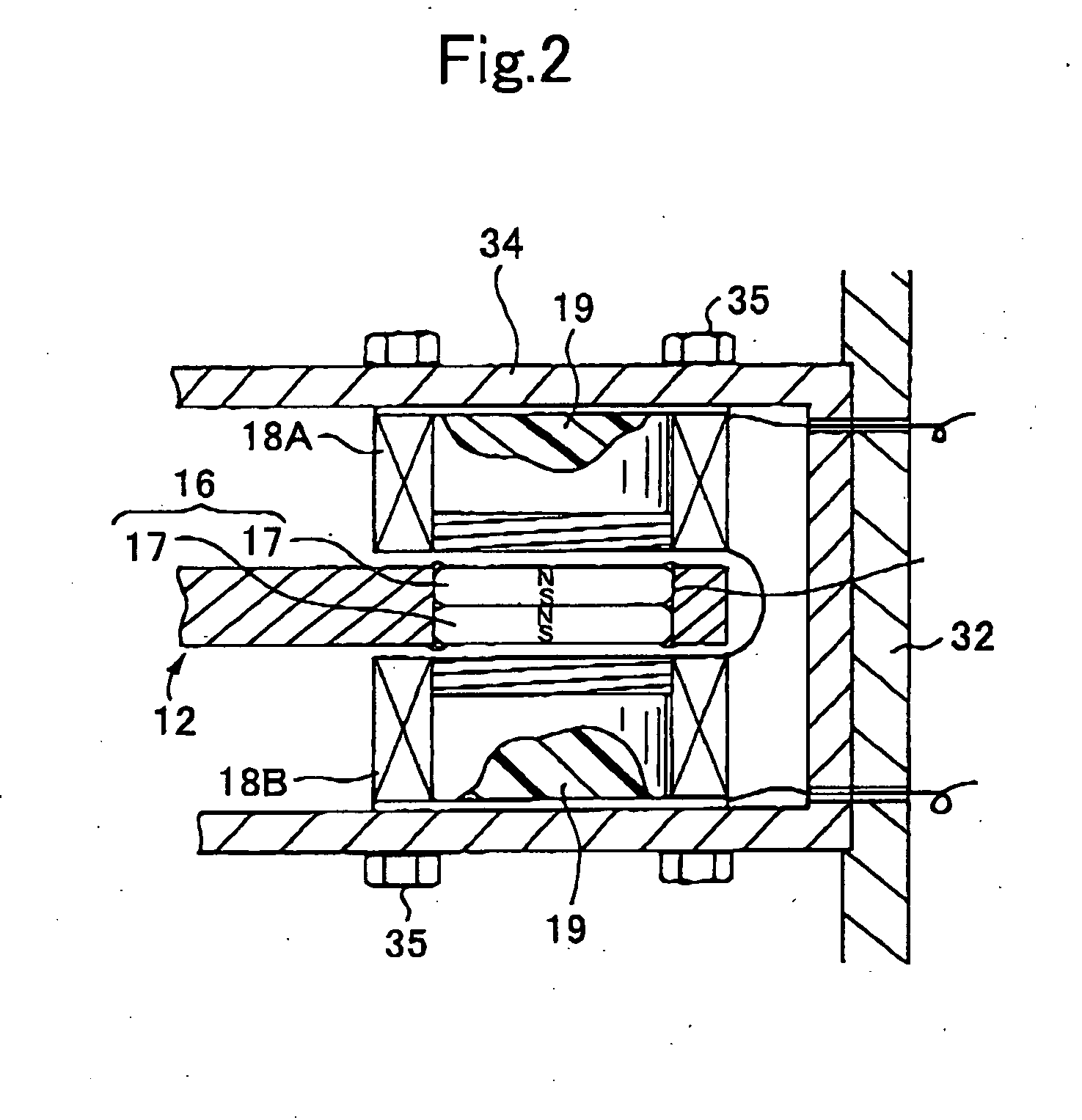
[0115] Two disc-shaped aluminum rotors having a diameter of 120 cm and a thickness of 20 mm were prepared. A driven rotor for a torque amplifier was formed of an aluminum disc-shaped plate having a diameter of 120 cm and a thickness of 20 mm. Each of a plurality of permanent magnets to be attached to the rotors, the driven rotor and a plurality of magnet wheels was formed by superimposing three doughnut-shaped neodymium-based (Nd—Fe-Bo) magnets (NEOMAX available from Sumitomo Special Metals Co., Ltd.) having an outer diameter of 76 mm, an inner diameter of 42 mm and a thickness of 6 mm. The permanent magnet had magnetic characteristics including a magnetic flux density KG of 3.5 and a magnetic force of 55 Kg. An annular zone was defined in each of the rotors in such a manner that the center of the width thereof along the outer periphery of the rotor has a radius of 55 cm from the rotational axis of the rotor 72 of the permanent magnets and 60 of permanent magnets were attached, resp...


PUM


Abstract

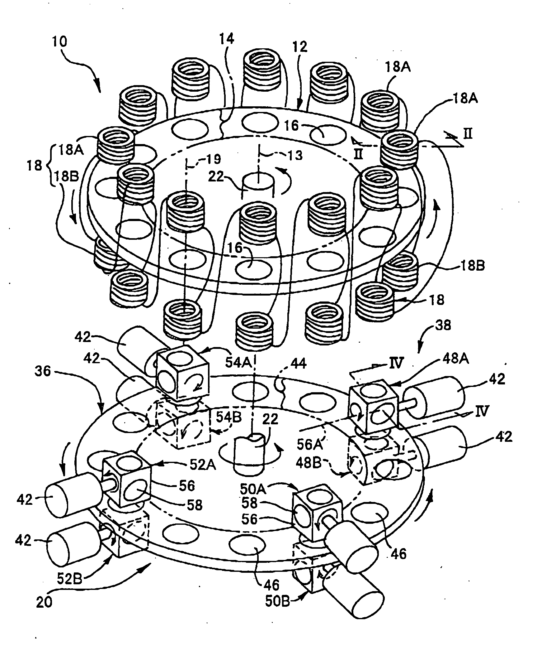
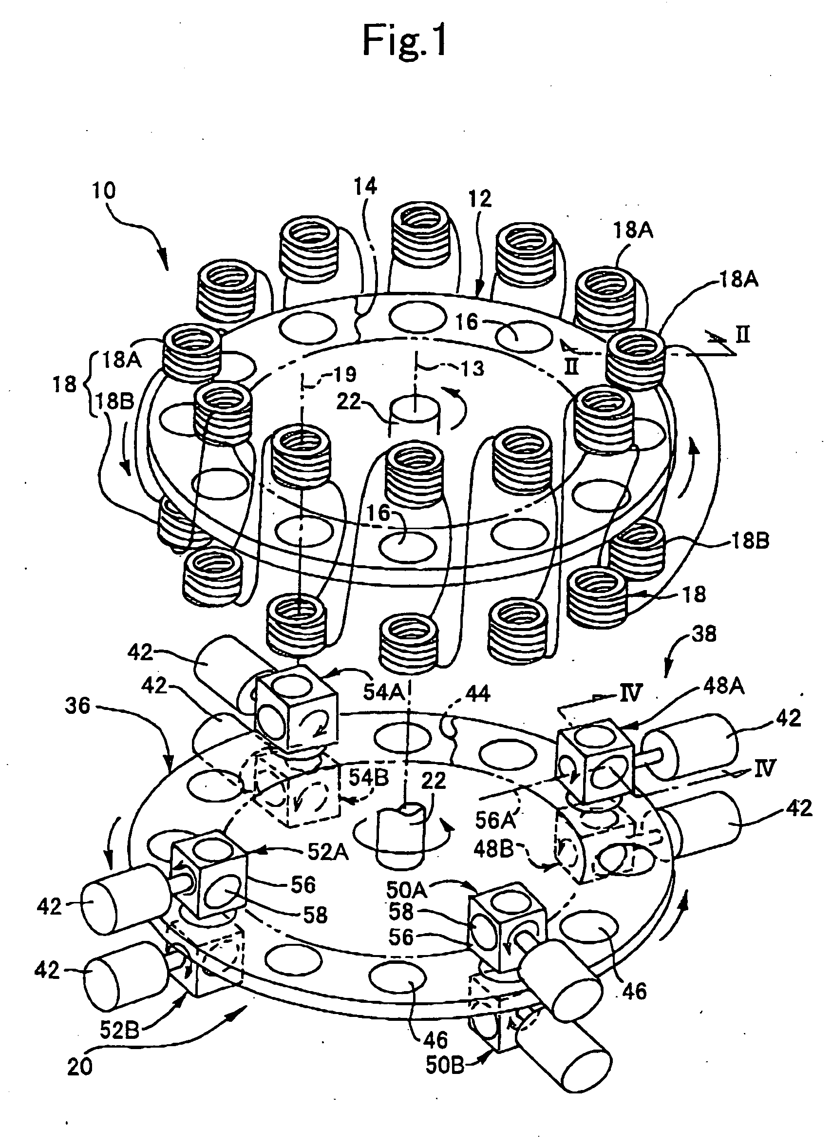
Disclosed is a power generator adapted to provide an electrical power greater than an input power by means of a permanent magnet. The power generator 10 comprises a rotatable rotor 12, a plurality of permanent magnets 16, and a plurality of coreless coils 18. The rotor 12 has a surface including an annular zone 14 formed around the rotational axis 13 thereof. The permanent magnets 16 are disposed along the annular zone 14 at constant intervals in the circumferential direction of the rotor 12 to form an annular array, while uniformly orienting their polarities in a direction orthogonal to the annular zone 14. The coreless coils 18 are supported by a stationary member 11 and disposed along the annular zone to form an annular array, while allowing the respective axes 19 of the coils to intersect with the annular zone 14. The permanent magnets 16 are moved along the coreless coils 18 in conjunction with the rotation of the rotor 12 induced by a rotational force supplied through a center shaft 22 from a torque amplifier 20 disposed below the rotor 12, so as to obtain an output power from the coreless coils 18.

Description

TECHNICAL FIELD [0001] The present invention relates to a power generator using a permanent magnet, and a torque amplifier suitable for use in driving-the power generator. BACKGROUND ART [0002] There has been known a torque multiplier or amplifier adapted, particularly, to obtain an output power greater than an external input power by means of a permanent magnet, such as a magnetic rotation apparatus disclosed in Japanese Patent Laid-Open Publication No. 09-285103. This magnetic rotation apparatus utilizes a repulsion force between a permanent magnet and an electromagnet or a repulsion force between a plurality of permanent magnets. There has also been known a power generator using a neodymium-based (Nd—Fe-Bo) magnet, such as a power generator disclosed in Japanese Patent Laid-Open Publication No. 10-191623, which is designed to lead a magnetic flux from respective poles of a rod-shaped neodymium-based magnet to a plurality of ferromagnetic members disposed in opposed relation to ea...

Claims


Application Information

Patent Timeline
Patent Type & Authority Applications(United States)
IPC IPC(8): H02K47/04H02K47/14H02K47/20H02K53/00
CPCH02K53/00
Inventor OGOSHI, MAKOTO
Owner OGOSHI MAKOTO
Learn More