

Electro-luminescence display device and driving apparatus thereof
a technology of electroluminescence display and driving apparatus, which is applied in the direction of static indicating devices, identification means, instruments, etc., can solve the problems of parasitic capacitance between adjacent data lines, picture quality deterioration phenomenon becomes particularly serious, and the driving time of pixels is reduced, so as to effectively charge and discharge a pixel
- Summary
- Abstract
- Description
- Claims
- Application Information
AI Technical Summary
Benefits of technology
Problems solved by technology
Method used
Image

Examples
first embodiment
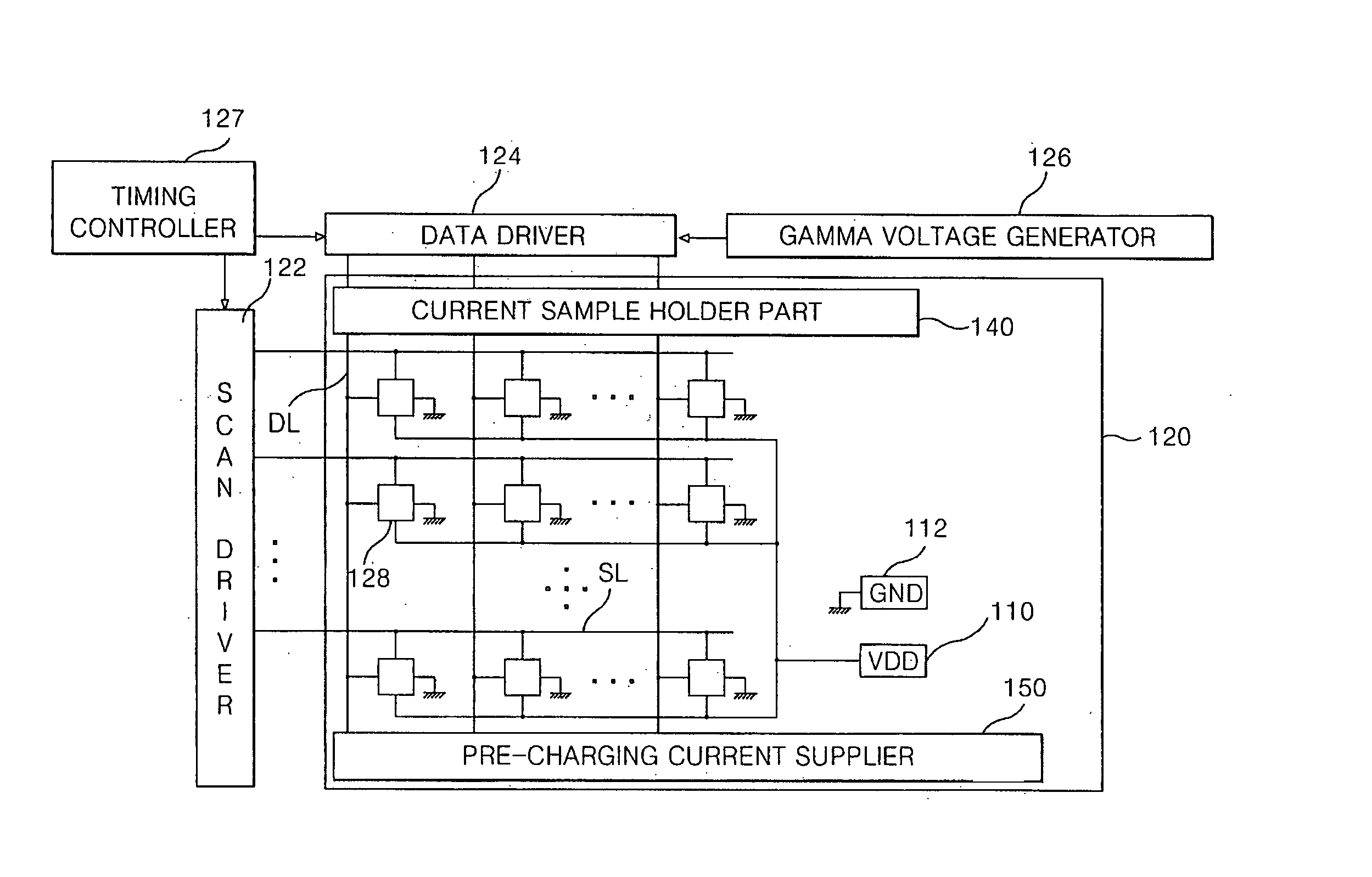
[0049]FIG. 4 is a schematic block diagram showing a configuration of an electro-luminescence display device according to the present invention. Referring to FIG. 4, an electro-luminescence (EL) display device according to an embodiment of the present invention includes an EL panel 120 having pixels 128 arranged between scan lines SL and data lines DL. A scan driver 122 drives the scan lines SL of the EL panel 120. A data driver 124 drives the data lines DL of the EL panel 120. A gamma voltage generator 126 supplies the data driver 124 with a plurality of gamma voltages. A current sample holder portion 140 is connected between the data driver 124 and the data line DL to pre-charge a driving current fed to the pixels 128. A pre-charging current supplier 150 is connected to the end of the data line DL to supply a pre-charging current to the data line DL. A timing controller 127 controls the data driver 124 and the scan driver 122. The current sample holder portion 140 and the pre-charg...
second embodiment
[0078] Unlike the related art EL display device, the EL display device according to the present invention, the pre-charger 250 and the current amplifier 260 amplifies a current value of a desired signal output from the driving circuit 280 and inputs it to the data line 225 of the EL panel 210 during a pre-charging period prior to a time when the data signal begins to be input to the switching thin film transistor, thereby allowing the data line 225 to have a value close to a desired voltage.
[0079] The data line 225 has already arrived at a value close to a desired voltage prior to a time when the data signal is input to the data line 225 so that it becomes possible to shorten a time when a data signal output from the data driver 220 after the pre-charging period is delivered via the data line 225 into the driving thin film transistor (not shown). Alternatively, even when the current amplifier only is used without the above-mentioned pre-charger, the amplified current flows into the ...
third embodiment
[0080]FIG. 14 is a timing diagram of driving signals for an EL display device according to the present invention. As shown in FIG. 14, a gate signal is sequentially input to the Nth scan line and the (N+1)th scan line of the EL panel 210 in response to a Nth scan clock GCLKN and a (N+1)th scan clock GCLKN+1. Thus, the switching thin film transistor connected to the Nth scan line and the switching thin film transistor connected to the (N+1)th scan line are sequentially turned on. If the Nth scan line is selected, then a data signal VIDEO is input, via the data line 225, to the switching thin film transistor during a first time interval t1 in response to a data clock DCLK.
[0081] In the third embodiment of the present invention, a certain period prior to the first interval t1 is set to a pre-charging interval t2. The pre-charger 250 and the current amplifier 260 are operated in response to a pre-charging signal ENA_PRE, thereby inputting the amplified current to the data line 225. Acco...
PUM
 Abstract
Description
Claims
Application Information