Lithographic apparatus, device manufacturing method, and device manufactured thereby

a technology of lithographic apparatus and manufacturing method, which is applied in the direction of photomechanical apparatus, instruments, optics, etc., can solve the problems of contaminated salt structures, lenses subject to intense radiation over a period of time, and loss of overall transmission and uniformity of wafer illumination, etc., to reduce the cost of fluid cleaning system, reduce the life of the apparatus, and eliminate the damage of expensive apparatus components

Inactive Publication Date: 2005-06-30
ASML NETHERLANDS BV
View PDF2 Cites 14 Cited by
  • Summary
  • Abstract
  • Description
  • Claims
  • Application Information

AI Technical Summary

Benefits of technology

[0025] This arrangement provides the advantage in that the fluid is cleaned to ultra high standards because the contaminant is retained in the cleaning zone. In particular, salt crystal growth which, after time, damages expensive apparatus compone

Problems solved by technology

It has been found that used G- and I-line and deep UV microlithography lenses suffer from degradation in terms of loss of overall transmission and loss of wafer illumination uniformity.
In a purged system, i.e., a system that is purged with a purging gas, this degradation is mainly caused by the occurrence of contamination on the surfaces of the first and last optical element in the projection system, i.e., the first optical element encountered by the projection beam and the last optical element encountered by the projection beam in the projection system.
It has been found that lenses subject to intense radiation over a period of time, typically a few years, become contaminated with salt structures.
It has been found, however, that this conventional approach results in a spreading or distribution o

Method used


Image

  • Lithographic apparatus, device manufacturing method, and device manufactured thereby
  • Lithographic apparatus, device manufacturing method, and device manufactured thereby
  • Lithographic apparatus, device manufacturing method, and device manufactured thereby

Examples


Embodiment Construction

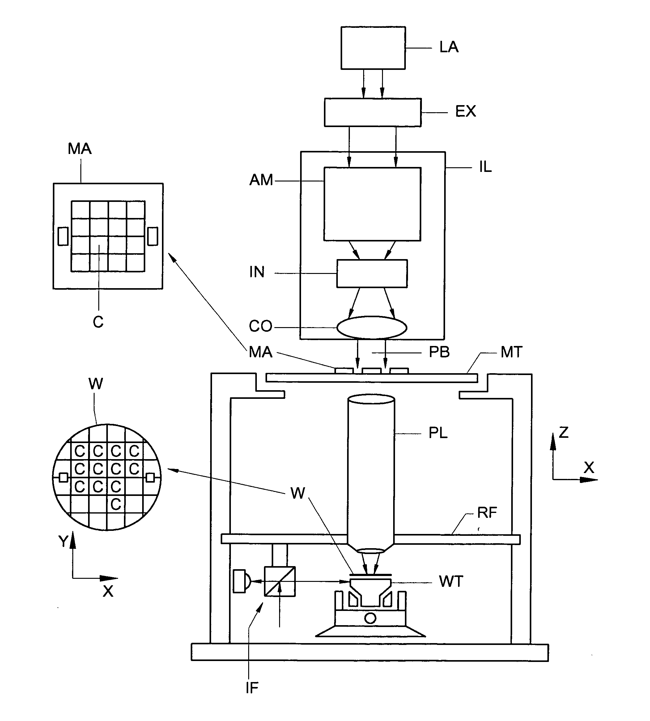
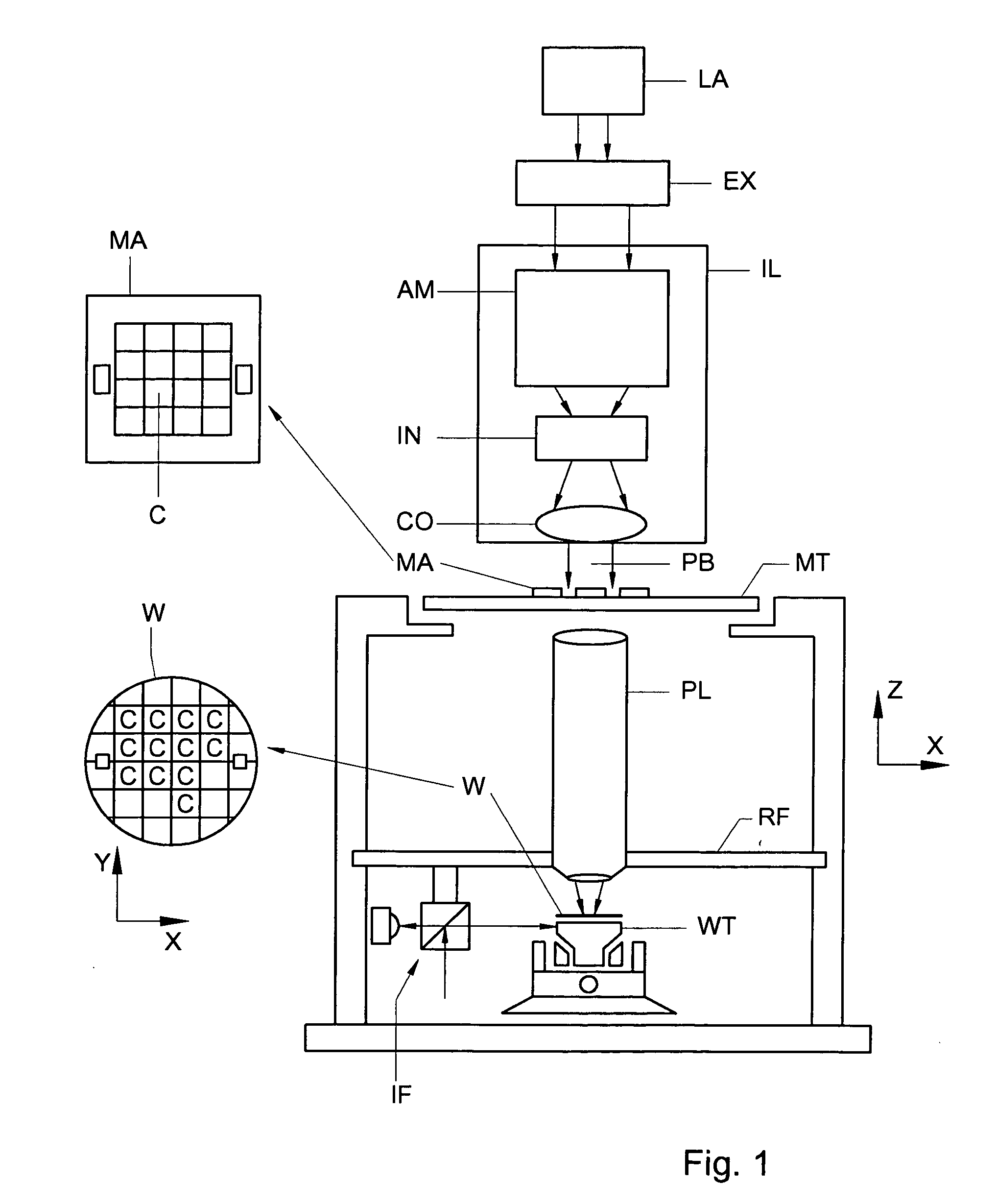
[0040]FIG. 1 schematically depicts a lithographic projection apparatus 1 according to a particular embodiment of the invention. The apparatus comprises: a radiation system Ex, IL, for supplying a projection beam PB of radiation (e.g. 365, 248, 193, 157 nm radiation). In this particular case, the radiation system also comprises a radiation source LA; a first object table (mask table) MT provided with a mask holder for holding a mask MA (e.g. a reticle), and connected to a first positioning device for accurately positioning the mask with respect to item PL; a second object table (substrate table) WT provided with a substrate holder for holding a substrate W (e.g. a resist coated silicon wafer), and connected to a second positioning device for accurately positioning the substrate with respect to item PL; and a projection system (“lens”) PL (e.g. an optical lens system) for imaging an irradiated portion of the mask MA onto a target portion C (e.g. comprising one or more dies) of the sub...


PUM


Abstract

A lithographic apparatus is disclosed. The apparatus includes a radiation system that provides a beam of radiation, and a support structure that supports a patterning structure. The patterning structure is configured to pattern the beam of radiation according to a desired pattern. The apparatus also includes a substrate support that supports a substrate, and a projection system that projects the patterned beam onto a target portion of the substrate. The projection system includes an optical element that has a beam entry area and an optical element that has a beam exit area through each of which the patterned beam passes. The apparatus further includes a nucleated surface that is associated with the projection system on which a plurality of nucleation sites are provided. The surface is disposed away from at least one of the beam entry area and the beam exit area.

Description

BACKGROUND OF THE INVENTION [0001] 1. Field of the Invention [0002] The present invention relates generally to a lithographic projection apparatus, and more specifically to a lithographic projection apparatus with a fluid cleaning system. [0003] 2. Description of Related Art [0004] The term “patterning device” or “patterning structure” as here employed should be broadly interpreted as referring to a device or structure that can be used to endow an incoming radiation beam with a patterned cross-section, corresponding to a pattern that is to be created in a target portion of the substrate. The term “light valve” can also be used in this context. Generally, the said pattern will correspond to a particular functional layer in a device being created in the target portion, such as an integrated circuit or other device (see below). Examples of such patterning devices include: [0005] A mask. The concept of a mask is well known in lithography, and it includes mask types such as binary, alter...

Claims


Application Information

Patent Timeline
IPC IPC(8): G03F7/20
CPCG03F7/70808G03F7/70983G03F7/70933G03F7/70916G03F7/20
Inventor KROON, MARKVAN BEEK, MICHAEL CORNELISDIRKSEN, PETERKURT, RALPHOWEN, CASSANDRA MAY
Owner ASML NETHERLANDS BV
Why Eureka
Try Eureka