Negative electrode for lithium secondary battery, method for manufacturing the same and lithium secondary battery

a secondary battery and negative electrode technology, applied in the direction of cell components, final product manufacturing, sustainable manufacturing/processing, etc., can solve the problems of battery charge-discharge cycle characteristics degradation, large degree of deformation, and often expansion/shrinkage of collectors, etc., to suppress the effect of deformation

Inactive Publication Date: 2005-06-30
PANASONIC CORP
View PDF0 Cites 45 Cited by
  • Summary
  • Abstract
  • Description
  • Claims
  • Application Information

AI Technical Summary

Benefits of technology

[0011] The object of the present invention is to provide a negative electrode for a lithium secondary battery capable of suppressing its deformation accompanying charging and discharging, a method for manufacturing the same and a lithium secondary battery using the same.

Problems solved by technology

Since the negative electrode in which the silicon thin film is formed on the collector has a high adhesion between the collector and the negative electrode material layer, the collector often expands / shrinks with the swelling and shrinkage of the negative electrode material.
Especially when a highly ductile metal foil such as a copper foil is used as the collector, the degree of deformation tends to be large.
This may cause a degradation of the charge-discharge cycle characteristics of the battery.
However, when a negative electrode material layer of a thin-film negative electrode material is formed on the collector made of such a mechanically-strong material, the adhesion between the negative electrode material layer and the collector becomes insufficient.
Consequently, there is a possibility that sufficient charge-discharge cycle characteristics cannot be achieved.
However, since the negative electrode suggested in the above document cannot suppress swelling / shrinkage of the negative electrode material accompanying charging and discharging, repeated charging and discharging may lower the adhesion between the negative electrode material layer and the collector.

Method used


Image

  • Negative electrode for lithium secondary battery, method for manufacturing the same and lithium secondary battery
  • Negative electrode for lithium secondary battery, method for manufacturing the same and lithium secondary battery
  • Negative electrode for lithium secondary battery, method for manufacturing the same and lithium secondary battery

Examples


example

[0087] The following is a more specific description of the present invention by way of an example. It should be noted that the present invention is not limited to the example below.

[0088] In the present example, 14 kinds of negative electrodes from Sample A to Sample N were produced and incorporated into a lithium secondary battery so as to evaluate battery characteristics (charge-discharge cycle characteristics). Further, a negative electrode of Sample O was produced as a comparative example and evaluated similarly. First, the methods for producing respective negative electrode samples will be described.

Sample A

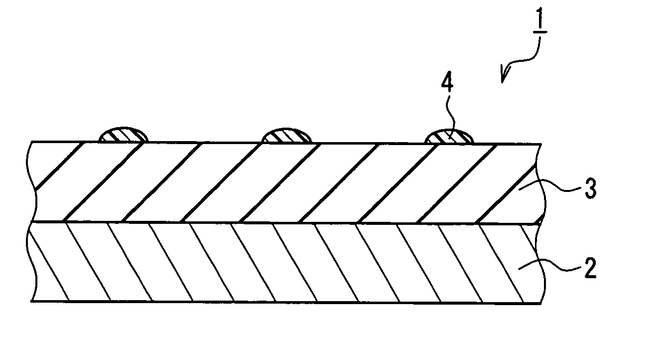
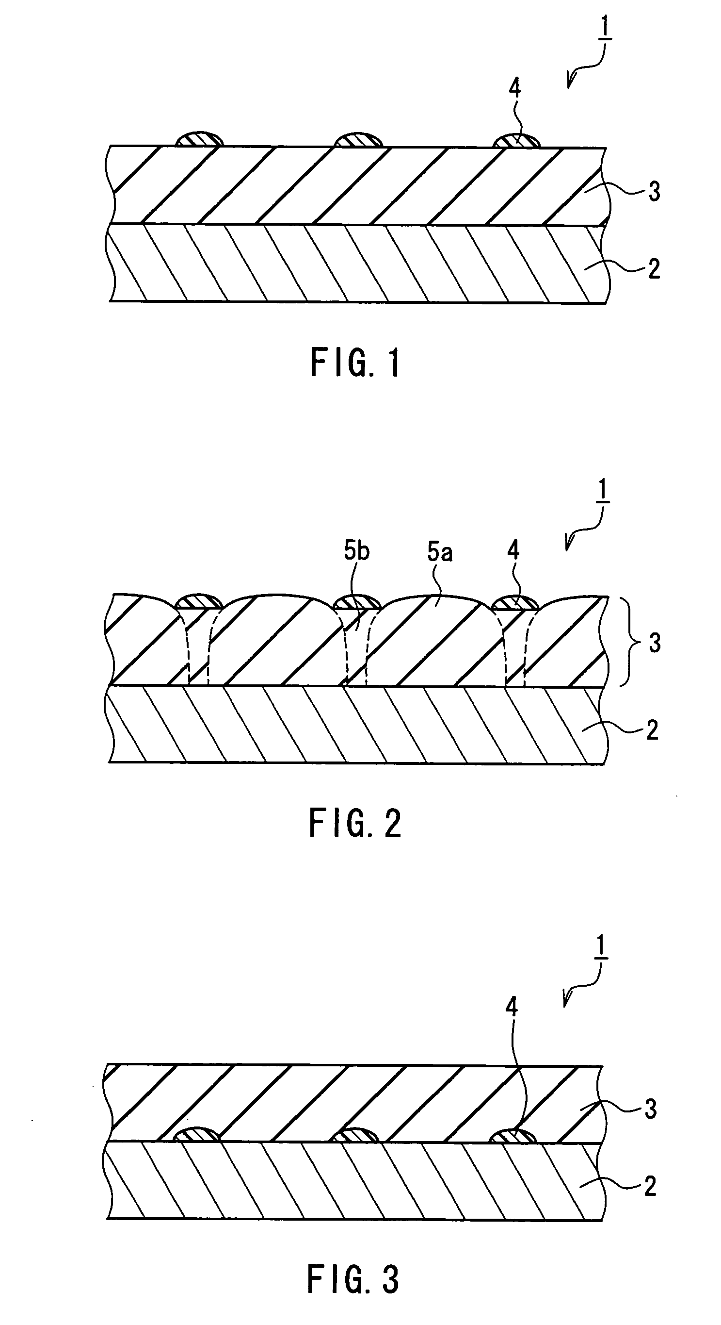
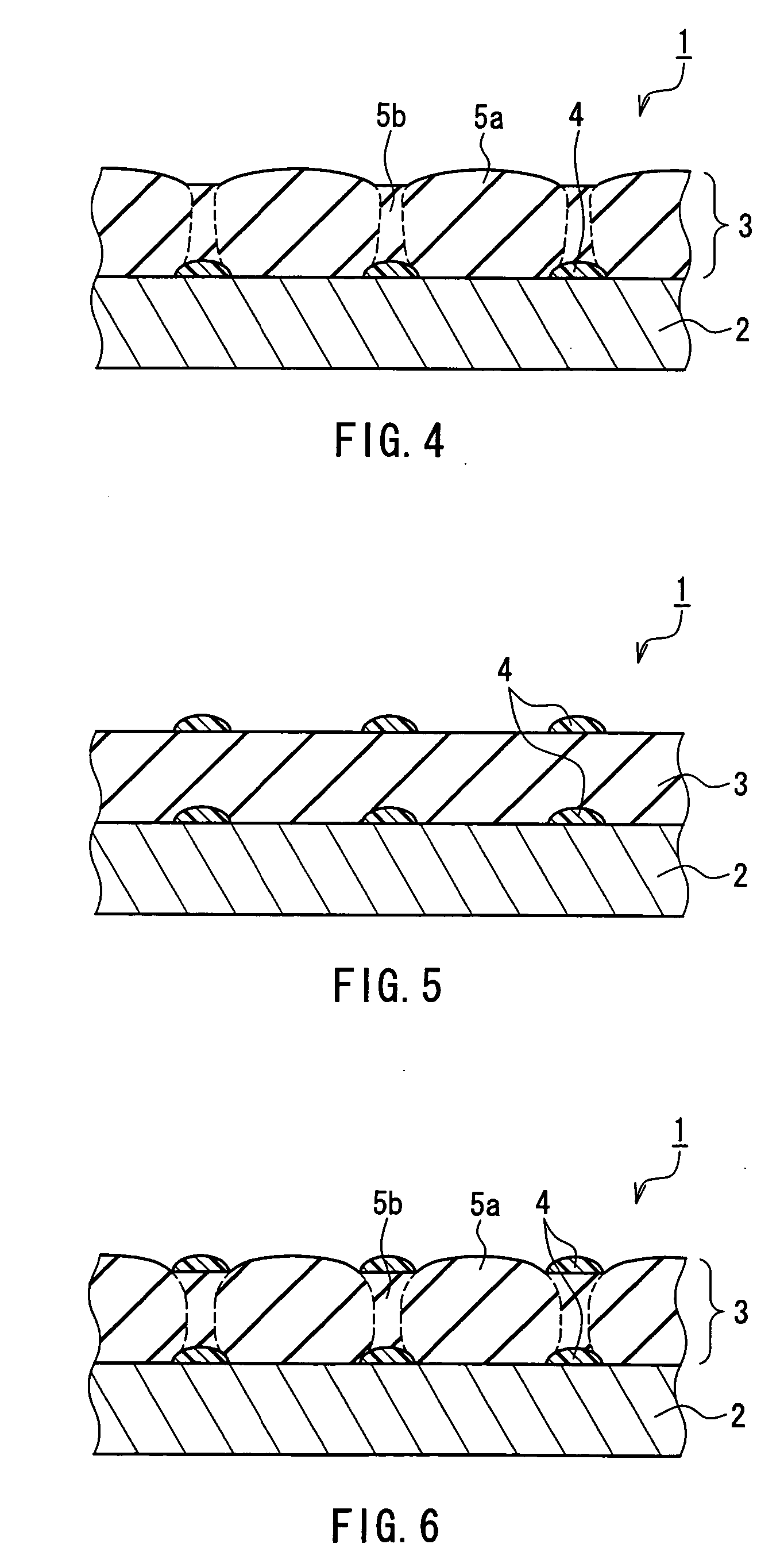
[0089] First, a silicon thin film (having a thickness of 10 μm) as a negative electrode material was layered on a collector (a copper foil having a thickness of 10 μm) by Radio Frequency (RF) sputtering using Ar gas plasma. In Sample A, the silicon thin film itself served as a negative electrode material layer (the same applies to the samples below).

[0090] Subsequently, ...


PUM

PropertyMeasurementUnit
areaaaaaaaaaaa
thicknessaaaaaaaaaa
thicknessaaaaaaaaaa

Abstract

A negative electrode for a lithium secondary battery capable of storing and releasing lithium reversibly includes a collector, and a negative electrode material layer arranged on the collector. The negative electrode material layer contains a thin-film negative electrode material capable of storing and releasing lithium reversibly, and lithium non-storing portions containing a lithium non-storing material are arranged on at least one selected from the group consisting of a surface and an inside of the negative electrode material layer. In this way, a negative electrode for a lithium secondary battery capable of suppressing the deformation accompanying charging and discharging is provided.

Description

BACKGROUND OF THE INVENTION [0001] 1. Field of the Invention [0002] The present invention relates to a negative electrode for a lithium secondary battery, a method for manufacturing the same and a lithium secondary battery using the same. [0003] 2. Description of Related Art [0004] In recent years, lithium secondary batteries have been studied and developed actively owing to their high output voltage and high energy density. In particular, there is a demand for lithium secondary batteries that have a low internal resistance and whose capacity does not drop very much due to charging and discharging (that have excellent charge-discharge cycle characteristics). [0005] For the purpose of achieving such lithium secondary batteries, a technology of using thin-film amorphous silicon or microcrystalline silicon for a negative electrode material (a negative active material) is known (for example, see JP 2002-83594 A). JP 2002-83594 A suggests a negative electrode for lithium secondary batter...

Claims


Application Information

Patent Timeline
Patent Type & Authority Applications(United States)
IPC IPC(8): B05D5/12H01M4/13H01M4/133H01M4/134H01M10/05H01M4/139H01M4/1393H01M4/1395H01M4/38H01M4/40H01M4/62H01M10/00
CPCH01M4/0404H01M4/0414H01M4/0426H01M4/0428Y02E60/122H01M4/1395H01M4/62H01M10/052H01M2004/027H01M4/134Y02E60/10Y02P70/50
Inventor NAKAI, MIYUKIIGAKI, EMIKOSHOJI, MASASHI
Owner PANASONIC CORP
Why Eureka
Try Eureka