Power transmission apparatus for vehicle and vehicle-driving electric machinery system using the same

Inactive Publication Date: 2005-06-30
HITACHI LTD
View PDF9 Cites 23 Cited by
  • Summary
  • Abstract
  • Description
  • Claims
  • Application Information

AI Technical Summary

Benefits of technology

[0008] However, when a planetary gearing is employed as the reduction gear unit as disclosed in the above-cited JP,A 2001-330111, one planetary gear set is constituted by an increased number of gears, i.e., one sun gear, one internal ring gear, and three or four pinion gears. Therefore, the number of mes

Problems solved by technology

Therefore, the number of meshes between the gears increases, and the power transmission efficiency of the reduction gear unit reduces.
In addition, because the planetary gearing includes a radial needle bearing and a thrust washer bearing for each of the three or four pinion gears, the power transmission efficiency further reduces.
On the other hand, because there is a limitation in reducing the diameter of the sun gear S from the viewpoint of design, the diameter of the internal ring gear R must be increased to reduce the gear ratio ρ. However, increasing the diameter of the internal ring gear R is

Method used


Image

  • Power transmission apparatus for vehicle and vehicle-driving electric machinery system using the same
  • Power transmission apparatus for vehicle and vehicle-driving electric machinery system using the same
  • Power transmission apparatus for vehicle and vehicle-driving electric machinery system using the same

Examples


first embodiment

[0038] The construction of a power transmission apparatus for vehicle according to the present invention will be described below with reference to FIGS. 1 to 8. This embodiment is described, by way of example, in connection with the case in which respective axes of a motor shaft and an output shaft of a differential gear unit are parallel to each other.

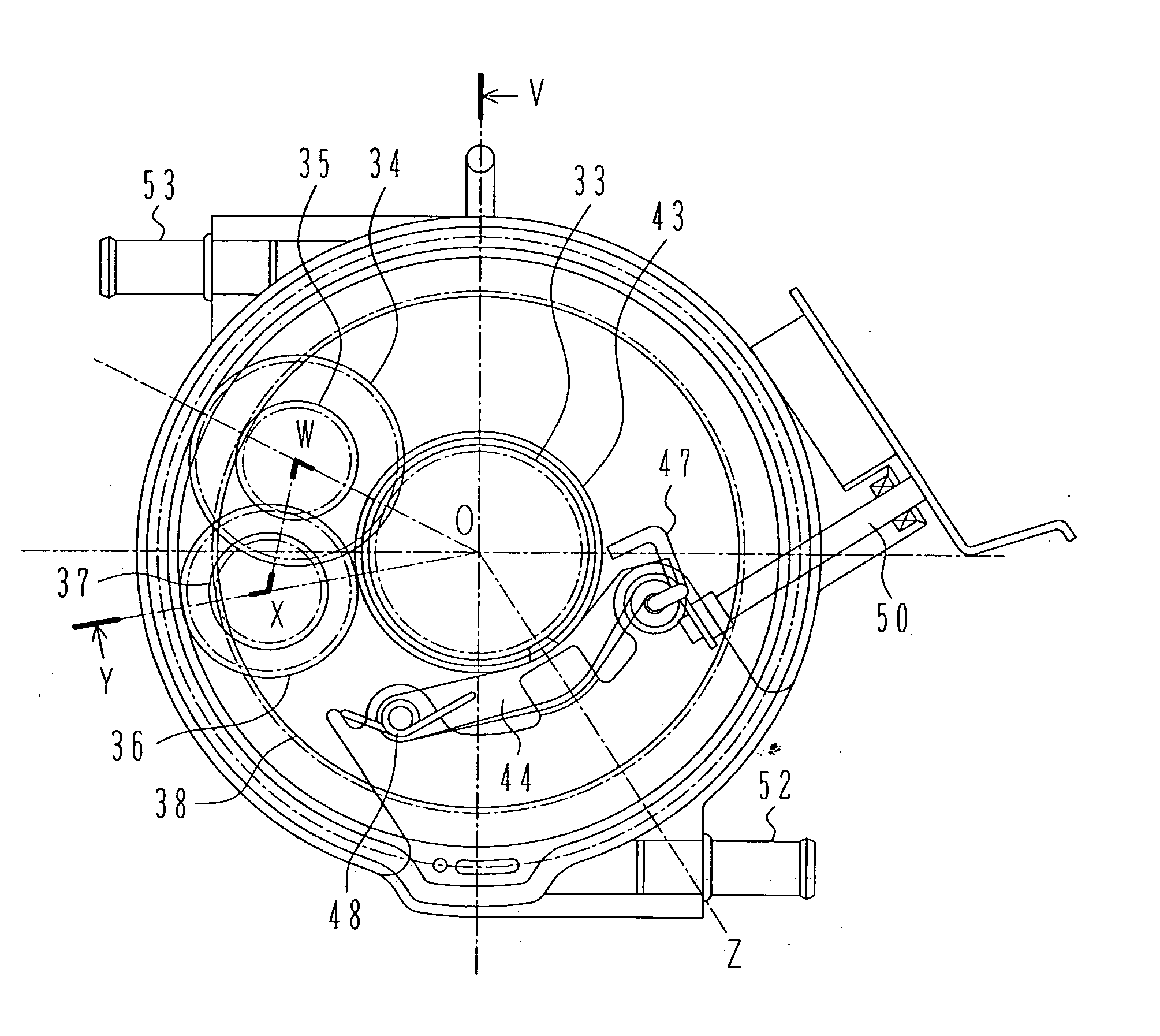
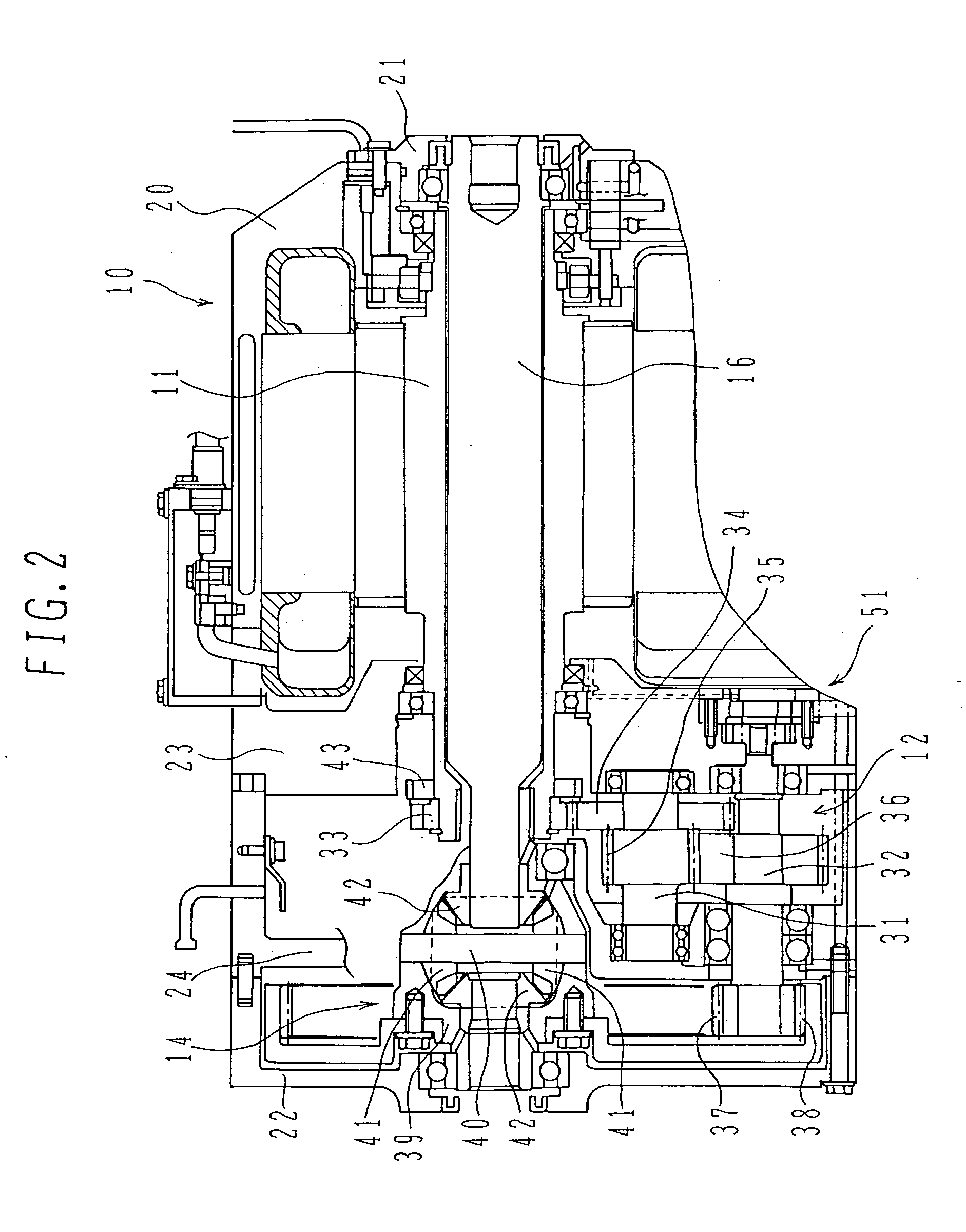
[0039]FIG. 1 is a front view of the power transmission apparatus for vehicle according to the first embodiment of the present invention, and FIG. 2 is a side view taken along a section V-O-W-X-Y in FIG. 1. FIG. 3 is a schematic functional view taken along the section V-O-W-X-Y in FIG. 1, and FIG. 4 is a front view of a vehicle driving system using the power transmission apparatus for vehicle according to the first embodiment of the present invention.

[0040] In FIGS. 2 and 3, a motor 10 is rotatable in forward and backward directions. Torque power outputted from the motor 10 is reduced in speed (decelerated) by a reduction gear unit 12...

second embodiment

[0068]FIG. 9 is a schematic view showing the construction of the power transmission apparatus for vehicle according to the present invention. In FIG. 9, the same symbols as those in FIG. 3 denote the same components.

[0069] A motor 10 is rotatable in forward and backward directions. Torque power outputted from the motor 10 is reduced in speed by a reduction gear unit 60 and then distributed to left and right driving systems through a differential gear unit 61 having an axis perpendicular to an axis of the motor 10. In a similar way to that described above with reference to FIG. 4, two outputs distributed to left and right driving systems through the differential gear unit 61 are coupled to drive shafts (not shown) and then transmitted to driving wheels (not shown). A housing 71 constituting a part of the reduction gear unit 60 has a diameter equal to or smaller than that of a cylindrical housing 20 constituting a part of the motor 10.

[0070] The reduction gear unit 60 comprises one s...

third embodiment

[0095] The gear layout as another feature of the power transmission apparatus for vehicle according to the present invention will be described below with reference to FIGS. 12 to 14.

[0096] First, with reference to FIG. 12, a description is made of the gear layout in the power transmission apparatus for vehicle according to the third embodiment of the present invention.

[0097]FIG. 12 is a front view for explaining the gear layout in the power transmission apparatus for vehicle according to the third embodiment of the present invention.

[0098] The gear A 33 mounted over the output shaft 11 of the motor 10 meshes with the gear B 34 of the reduction gear unit 12. The gear C 35 being coaxial with the gear B 34 meshes with the gear D 36. The gear E 37 being coaxial with the gear D 36 meshes with the internal ring gear F 38 of the differential gear unit 14. The internal ring gear F 38 drives the pinion gears 41. Note that a circle indicating each of the gears 33, 34, 35, 36, 37, 38 and 41 ...


PUM


Abstract

The invention provides a power transmission apparatus for vehicle which can realize a high torque transmission efficiency and a high reduction gear ratio of a reduction gear unit with a more compact structure, and a vehicle-driving electric machinery system using the power transmission apparatus for vehicle. The power transmission apparatus for vehicle comprises a motor, a reduction gear unit for decelerating power outputted from the motor, and a differential gear unit for distributing the power decelerated by the reduction gear unit to left and right wheels. The reduction gear unit is a reduction gear mechanism including a plurality of gears mounted over a shaft which is rotatably held by a housing in a fixed position. The reduction gear unit and the differential gear unit are arranged within an area in oppositely facing relation to an axial end surface of the motor.

Description

BACKGROUND OF THE INVENTION [0001]1. Field of the Invention [0002] The present invention relates to a power transmission apparatus for vehicle employing a motor as a power source, and to a vehicle-driving electric machinery system using the power transmission apparatus for vehicle. More particularly, the present invention relates to a power transmission apparatus for vehicle suitable for use in a vehicle including a reduction gear unit and a differential gear unit, and to a vehicle-driving electric machinery system using the power transmission apparatus for vehicle. [0003] 2. Description of the Related Art [0004] In a known power transmission apparatus for vehicle employing a motor as a power source, output power of the motor is transmitted to driving wheels through a reduction gear unit to produce a large driving torque, as disclosed in, e.g., JP,A 2001-330111 and JP,A 8-230489. [0005] The system disclosed in JP,A 2001-330111 employs, as the reduction gear unit, a mechanism compris...

Claims


Application Information

Patent Timeline
IPC IPC(8): B60K1/00B60K6/36B60K6/365B60K6/40B60K6/44B60K6/52B60K6/547B60K17/04B60K17/16B60K17/356F16H1/10F16H48/08F16H48/40F16H48/42
CPCB60K6/44B60K6/40B60K6/547B60K17/04B60K17/16B60K17/356F16H1/10F16H48/08F16H48/42F16H2048/082F16H2048/405F16H2048/423Y02T10/623Y02T10/6265B60K1/00B60K6/36B60K6/365B60K6/52Y02T10/62
Inventor HAMAI, KYUGOSEKIGUCHI, HIDEKIMIYAMOTO, SHOGOTANAKA, YOSHIKAZU
Owner HITACHI LTD
Why Eureka
Try Eureka