Control device for hydraulic winch

a control device and hydraulic winch technology, applied in the direction of braking system, servomotor, hoisting equipment, etc., can solve the problems of slow control response, load to swing, and the speed control range at the same amount of supplied oil cannot be expanded

Active Publication Date: 2005-06-30
KOBELCO CONSTR MASCH CO LTD
View PDF5 Cites 9 Cited by
  • Summary
  • Abstract
  • Description
  • Claims
  • Application Information

AI Technical Summary

Benefits of technology

[0034] In addition, in the above-described structure, the motor-capacity controlling means may include a regulator for varying the tilting angle of the hydraulic motor in res

Problems solved by technology

However, the above-described structure has the following problems:
For example, during winding-up of a large load, combined control of lowering a boom and winding-up with a winch can cause the load to swing.
Therefore, a high load pre

Method used


Image

  • Control device for hydraulic winch
  • Control device for hydraulic winch
  • Control device for hydraulic winch

Examples


first embodiment (see figs.1 to 3)

First Embodiment (See FIGS. 1 to 3)

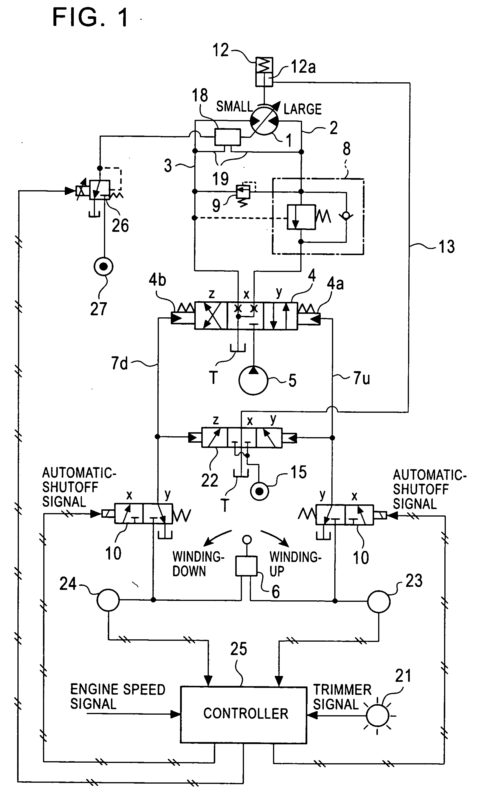
[0043] In FIG. 1, a hydraulic motor 1 having variable capacity functions as a driving source of a winch. Both a winding-up side pipeline 2 and a winding-down side pipeline 3 of the hydraulic motor 1 are connected to a hydraulic pump 5 via a control valve 4 of a hydraulic pilot switching type having three switching positions x, y, and z for a neutral state, winding-up, and winding-down, respectively. This control valve 4 controls supply and discharge of pressurized oil to the hydraulic motor 1 (driving and halting of the hydraulic motor 1, and the rotating direction and speed at the time of driving).

[0044] A remote-control valve 6 functions as operating means for switching the position of the control valve 4 to the winding-up position or the winding-down position. A remote-control pressure generated by the operation of the remote-control valve 6 is transmitted to both a winding-up side pilot port 4a of the control valve 4 via a remote-control press...

second embodiment (see fig.4)

Second Embodiment (See FIG. 4)

[0074] Only differences from the first embodiment will be described.

[0075] According to the first embodiment, the hydraulic power source 27 supplies a hydraulic pressure to the regulator 18 via the regulator-controlling valve 26. Accordingly, if the regulator-controlling valve 26 fails when a small-capacity command is issued, as is often the case with electromagnetic valves, the regulator 18 cannot set a large capacity at the automatic shutoff.

[0076] Therefore, an inlet port 26a of the hydraulic power source of the regulator-controlling valve 26 is connected to the pressure chamber 12a of the negative brake 12 in a second embodiment.

[0077] With this arrangement, when the negative brake 12 is activated, the hydraulic pressure in the pressure chamber 12a and thus the hydraulic pressure in the regulator-controlling valve 26 are released. As a result, even if the regulator-controlling valve 26 fails at a small-capacity command, the regulator-controlling v...

third embodiment (see fig.5)

Third Embodiment (See FIG. 5)

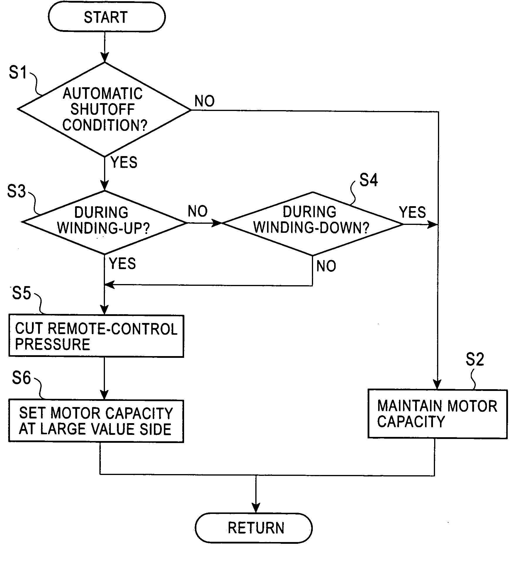
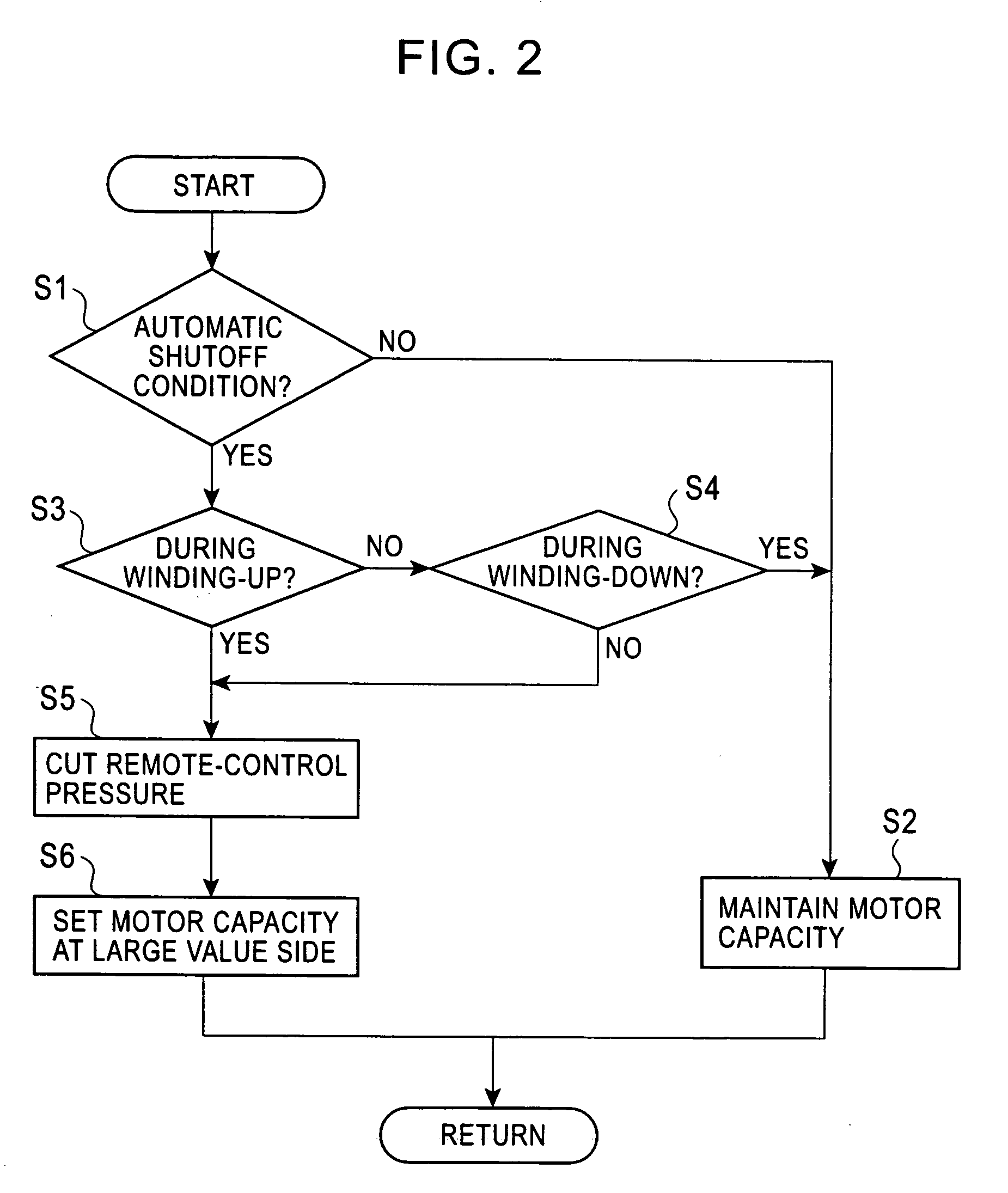
[0078] According to the first and second embodiments, the controller 25 outputs a command signal to the regulator-controlling valve 26 to set the hydraulic motor 1 at a large capacity immediately after the activation of the negative brake 12 at the automatic shutoff. In contrast, according to a third embodiment, an operation signal of the remote-control valve 6, i.e. the remote-control pressure, is cut at the automatic shutoff to set the hydraulic motor 1 at a large capacity.

[0079] Specifically, the remote-control pressure lines 7u and 7d are connected to the regulator 18 via a shuttle valve 17, an electromagnetic switching valve 28 controlled by the controller 25, and a readout line 29 for reading out the remote-control pressure. With this arrangement, the motor capacity is decreased as the amount of the operation of the remote-control valve 6 is increased.

[0080] The switching valve 28 is normally connected to the shuttle valve 17 and the readout line...


PUM


Abstract

According to a control device for a hydraulic winch of the present invention, a regulator controls a motor capacity of a hydraulic motor having variable capacity functioning as a driving source of the hydraulic winch in response to a load pressure, a negative brake stops and retains the hydraulic motor at an automatic shutoff for prevention of overloading, and a controller sends signals to the regulator via a regulator-controlling valve at the automatic shutoff to set the motor capacity at a large value. Thus, the delay to recover the motor capacity at the time of returning from the automatic shutoff that is activated during winding-up of a load does not occur, and a control response is increased.

Description

BACKGROUND OF THE INVENTION [0001] 1. Field of the Invention [0002] The present invention relates to control devices for hydraulic winches for controlling winding-up / winding-down operations of winch drums by hydraulic motors having variable capacity functioning as power sources. [0003] 2. Description of the Related Art [0004] A hydraulic motor having variable capacity is often used as a driving source of a hydraulic winch for varying speed and power of winding-up / winding-down in response to a load. The structure of an exemplary device is shown in FIG. 6. [0005] A negative brake 12 for maintaining a hydraulic motor 1 in a halt state is provided on the hydraulic motor 1. This negative brake 12 is activated when a brake valve 14 shifts from a brake-releasing position x to a brake-activating position y to release the hydraulic pressure in a pressure chamber 12a into a tank T. [0006] A switching valve 16 is controlled by a signal from a controller 11. At the time of an automatic shutoff,...

Claims


Application Information

Patent Timeline
IPC IPC(8): B66D1/08B66D1/44B66D1/48F15B11/02F15B11/08
CPCB66D1/08B66D1/44B66D1/48Y10T477/6388Y10T477/814Y10T477/813Y10T477/86
Inventor SHIMOMURA, KOICHIEHARA, MASAAKI
Owner KOBELCO CONSTR MASCH CO LTD
Why Eureka
Try Eureka