Stress reduction apparatus and method

a stress reduction and apparatus technology, applied in the field of apparatus for treating a failing heart, can solve the problems of increasing the requirement for systolic contraction, increasing the wall tension and/or stress, and the heart continues to dilate, so as to reduce the maximum wall stress experience

Inactive Publication Date: 2005-06-30
EDWARDS LIFESCIENCES LLC
View PDF99 Cites 88 Cited by
  • Summary
  • Abstract
  • Description
  • Claims
  • Application Information

AI Technical Summary

Benefits of technology

[0010] The present invention pertains to a device and method for reducing mechanical heart wall muscle stress. Heart muscle stress is a stimulus for the initiation and progressive enlargement of the left ventricle in heart failure. Reduction of heart wall stress with the devices and methods disclosed herein is anticipated to substantially slow, stop or reverse the heart failure disease process. Although the primary focus of the discussion of the devices and methods of the present invention herein relates to heart failure and the left ventricle, these devices and method could be used to reduce stress in the heart's other chambers.
[0011] The devices and methods of the present invention can reduce heart wall stress throughout the cardiac cycle including end diastole and end systole. Alternatively, they can be used to reduce wall stress during the portions of the cardiac cycle not including end systole. Those devices which operate throughout the cardiac cycle are referred to herein as “full cycle splints”. Those devices which do not operate to reduce wall stress during end stage systole are referred to as “restrictive devices”. Restrictive devices include both “restrictive splints” which alter the geometric shape of the left ventricle, and “wraps” which merely limit the magnitude of the expansion of the left ventricle during diastolic filling without a substantial shape change.
[0012] While it is desirable to reduce wall stress for the treatment of heart failure, to slow or reverse the disease process and to increase heart wall muscle shortening and pumping efficiency, it is also desirable to maintain or improve stroke volume and allow for variable preload.
[0014] In asymtomatic, early stage heart failure, it may be possible to use only a restrictive device or method as elevated wall stress is considered to be an initiator of muscle damage and chamber enlargement. Restrictive devices and methods acting during diastole will reduce the maximum wall stress experience during end diastole and early systole. It should be understood that restrictive devices and methods can be used in combination with full cycle splinting to more precisely control or manipulate stress reduction throughout the cardiac cycle.

Problems solved by technology

With damage to the myocardium or chronic volume overload, however, there are increased requirements put on the contracting myocardium to such a level that this compensated state is never achieved and the heart continues to dilate.
The basic problem with a large dilated left ventricle is that there is a significant increase in wall tension and / or stress both during diastolic filling and during systolic contraction.
However, in a failing heart, the ongoing dilatation is greater than the hypertrophy and the result is a rising wall tension requirement for systolic contraction.
This is felt to be an ongoing insult to the muscle myocyte resulting in further muscle damage.
Additionally, because of the lack of cardiac output, there is generally a rise in ventricular filling pressure from several physiologic mechanisms.
These drug therapies offer some beneficial effects but do not stop the progression of the disease.
Heart transplantation has serious limitations including restricted availability of organs and adverse effects of immunosuppressive therapies required following heart transplantation.
However, this extremely invasive procedure reduces muscle mass of the heart.

Method used


Image

  • Stress reduction apparatus and method
  • Stress reduction apparatus and method
  • Stress reduction apparatus and method

Examples


embodiment 110

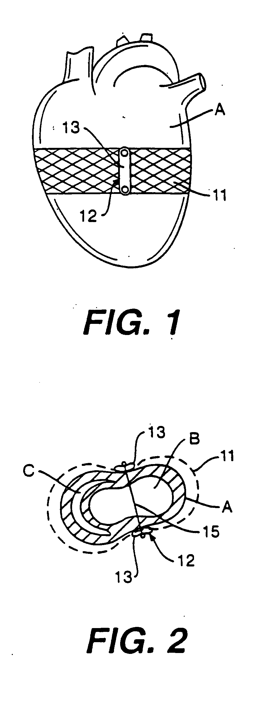
[0095]FIG. 17 is an alternate embodiment 110 of the band splint of FIG. 16. Band splint 110 includes a horizontally heart encircling band 111 and four bands 113 extending downward from band 111. Bands 113, however, unlike bands 102 of band splint 100 do not extend to the apex of heart A, but rather to a second horizontally heart encircling band 112.

[0096] Band splint 110 could be made of the same materials as band splint 100. Band splint 110 can also be used in a manner similar to band splint 100 except that band splint 110 would limit the vertical elongation of the ventricles less than band splint 100.

[0097]FIG. 18 is yet another alternate embodiment 120 of the wrap of FIG. 16. Band splint 120 closely resembles alternate embodiment 110 of FIG. 17, except that rather than having four vertically extending web members, band splint 120 includes two substantially rigid members 123 interconnecting two horizontally encircling web members 121 and 122.

[0098]FIG. 19 is yet another alternat...

embodiment 170

[0106]FIG. 27 is an alternate embodiment 170 of the wrap of FIG. 26. Wrap 170, however, includes two vertically extending bars 172 having eyelets 173 through which line 171 is threaded. Line 171 can be tied to one of the bars 172 at 174 and 175.

[0107]FIG. 28 is a vertical view of heart A including yet another embodiment 180 of the wrap of FIG. 26. Wrap 180 includes a line 181 encircling heart A a plurality of times. Rather than having a single vertically extending bar 162 to position line 180 on heart A, wrap 180 includes a plurality of horizontal bars 182 including a pair of eyelets 183. One end of line 181 is tied to an upper bar 182 at 184 and the opposite end of line 181 is tied to a lower bar 182 at 185. Between 184 and 185, line 181 is threaded through eyelets 182 to form the heart encircling pattern shown in FIG. 28.

[0108]FIG. 29 is a vertical view of heart A including yet another alternate embodiment 190 of the wrap of FIG. 26. Wrap 190 closely resembles 180 of FIG. 28. Lin...

embodiment 270

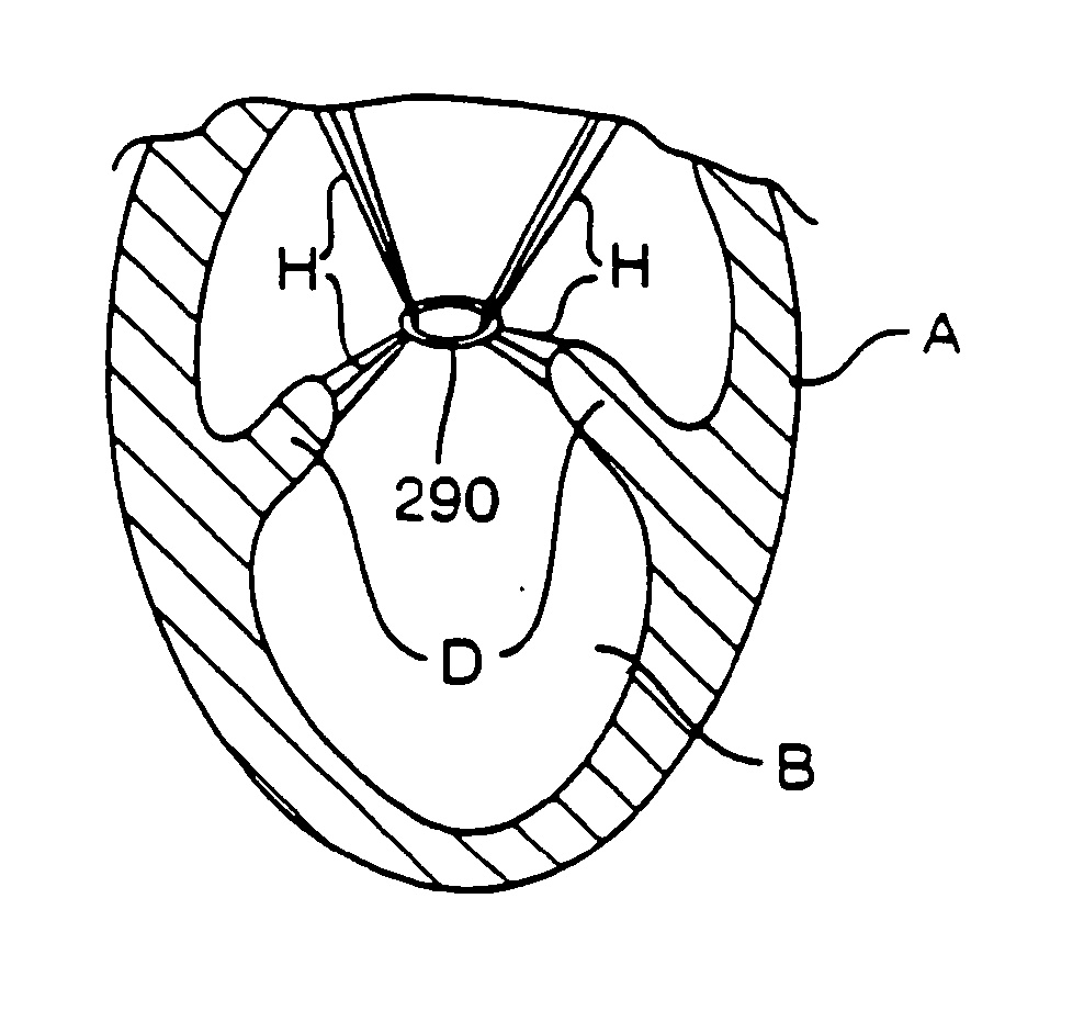
[0124]FIG. 43 is a horizontal cross sectional view of heart A including left ventricle B and right ventricle C and an alternate embodiment 270 of the device of FIG. 42. Device 270 includes a line 271 which does not extend transventricularly but extends through the myocardium of heart A to form four loops 273.

[0125] Device 270 can be formed from material similar to that used to form device 260. Additionally, device 270 can be made to function as a restrictive device or full cycle device in a manner similar to that of device 260.

[0126] Line 261 and line 267 could be disposed within a tube such as tube 231 of FIG. 38 to avoid cheese cutting of the myocardium. Devices 260 and 270 could extend through the septum or right ventricle to avoid forming lobes in right ventricle C.

[0127]FIG. 44 is a vertical view of heart A including three devices 270 disposed at three spaced elevations. An elongate generally rigid bar 274 is disposed through loops 273 to distribute the load on heart A from l...


PUM


Abstract

The device and method for reducing heart wall stress. The device can be one which reduces wall stress throughout the cardiac cycle or only a portion of the cardiac cycle. The device can be configured to begin to engage, to reduce wall stress during diastolic filling, or begin to engage to reduce wall stress during systolic contraction. Furthermore, the device can be configured to include at least two elements, one of which engages full cycle and the other which engages only during a portion of the cardiac cycle.

Description

RELATED APPLICATIONS [0001] This application is related to U.S. application Ser. No. ______, filed on date even herewith and entitled “Transventricular Implant Tools and Devices” and U.S. application Ser. No. ______, filed on date even herewith and entitled “Heart Wall Tension Reduction Apparatus and Method”, both of which are incorporated herein by referenceFIELD OF THE INVENTION [0002] The present invention pertains to the field of apparatus for treatment of a failing heart. In particular, the apparatus of the present invention is directed toward reducing the wall stress in the failing heart. BACKGROUND OF THE INVENTION [0003] The syndrome of heart failure is a common course for the progression of many forms of heart disease. Heart failure may be considered to be the condition in which an abnormality of cardiac function is responsible for the inability of the heart to pump blood at a rate commensurate with the requirements of the metabolizing tissues, or can do so only at an abnor...

Claims


Application Information

Patent Timeline
Patent Type & Authority Applications(United States)
IPC IPC(8): A61B17/00A61B17/04A61B17/122A61F2/00
CPCA61B17/00234A61B17/1227A61B2017/00243A61F2/2487A61B2017/048A61B2017/0496A61F2/2481A61B2017/0404
Inventor MORTIER, TODD J.SCHWEICH, CYRIL J. JR.VIDLUND, ROBERT M.
Owner EDWARDS LIFESCIENCES LLC
Why Eureka
Try Eureka