Ultrasonic image processing apparatus, ultrasonic image processing method and ultrasonic image processing program

a technology ultrasonic image, applied in the field of ultrasonic image processing apparatus, ultrasonic image processing method and ultrasonic image processing program, can solve the problems of inability to utilize the characteristics of original image data, the unclear outline of the structure or the like, and the change or loss of image characteristics of the original image data. to achieve the effect of improving the image quality of an ultrasonic imag

Active Publication Date: 2005-06-30
FUJIFILM HLDG CORP +1
View PDF8 Cites 70 Cited by
  • Summary
  • Abstract
  • Description
  • Claims
  • Application Information

AI Technical Summary

Benefits of technology

[0013] The present invention is achieved in view of the above-described problems. The first purpose of the present invention is to improve image quality of an ultrasonic image by performing image processing that utilizes image characteristics of the original image on the ultrasonic image obtained by transmitting and receiving ultrasonic waves. Further, the second purpose of the present invention is to provide an image processing method and so on by which artifacts are hardly generated when reduction of speckles is processed on the ultrasonic image obtained by transmitting and receiving ultrasonic waves.

Problems solved by technology

The speckle pattern acts as a kind of noise, and thereby, the demonstrated outline of the structure or the like often becomes unclear.
However, by such conversion of scan format, image characteristics (e.g., frequency bands and so on) of the original image data are sometimes changed or lost.
Accordingly, in the subsequent image processing like smoothing processing and edge enhancement processing including the morphology processing, it often occurs that characteristics of the original image data cannot be utilized.
Further, also in the morphology processing, the following problem occurs.

Method used


Image

  • Ultrasonic image processing apparatus, ultrasonic image processing method and ultrasonic image processing program
  • Ultrasonic image processing apparatus, ultrasonic image processing method and ultrasonic image processing program
  • Ultrasonic image processing apparatus, ultrasonic image processing method and ultrasonic image processing program

Examples


first embodiment

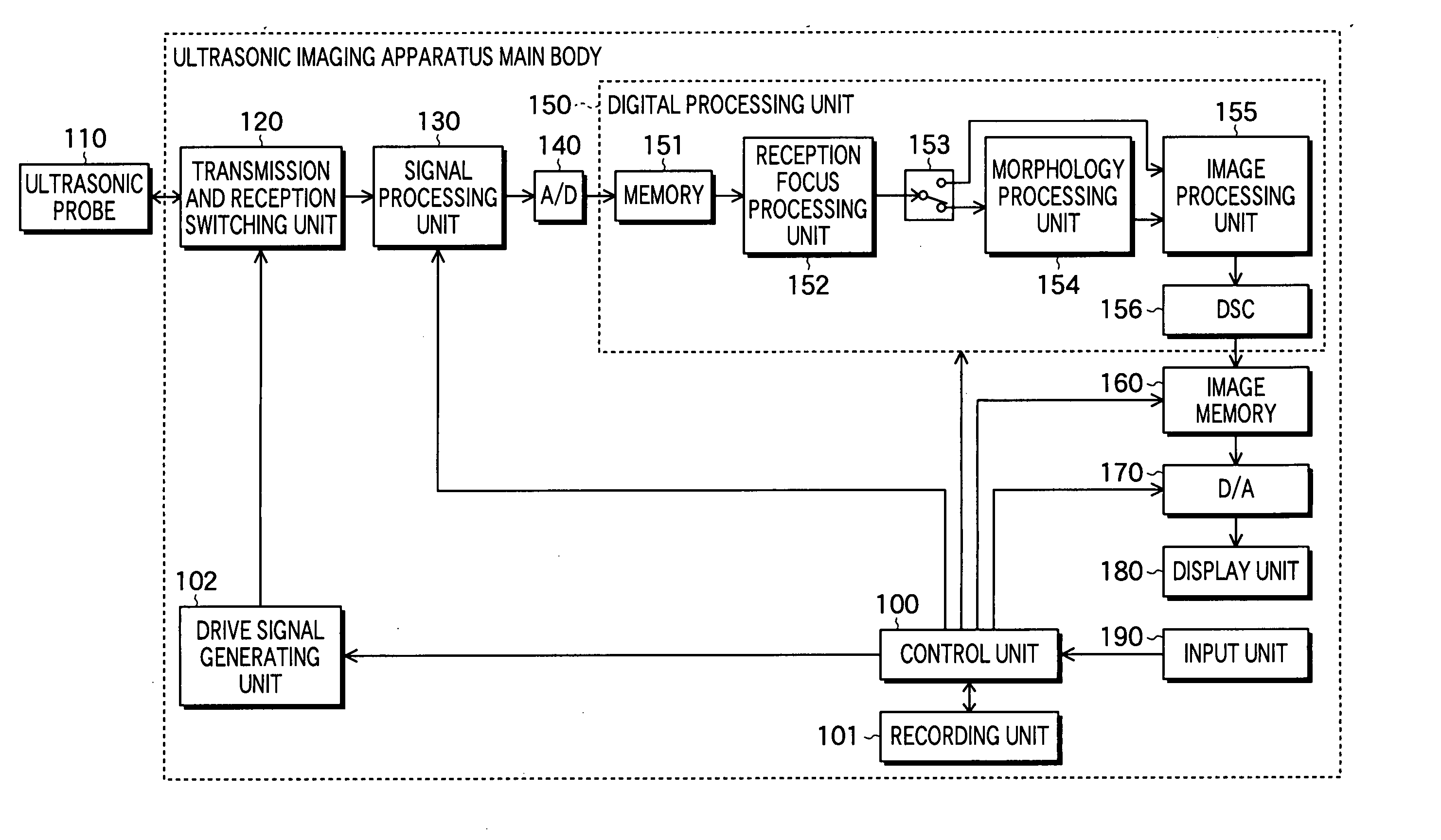
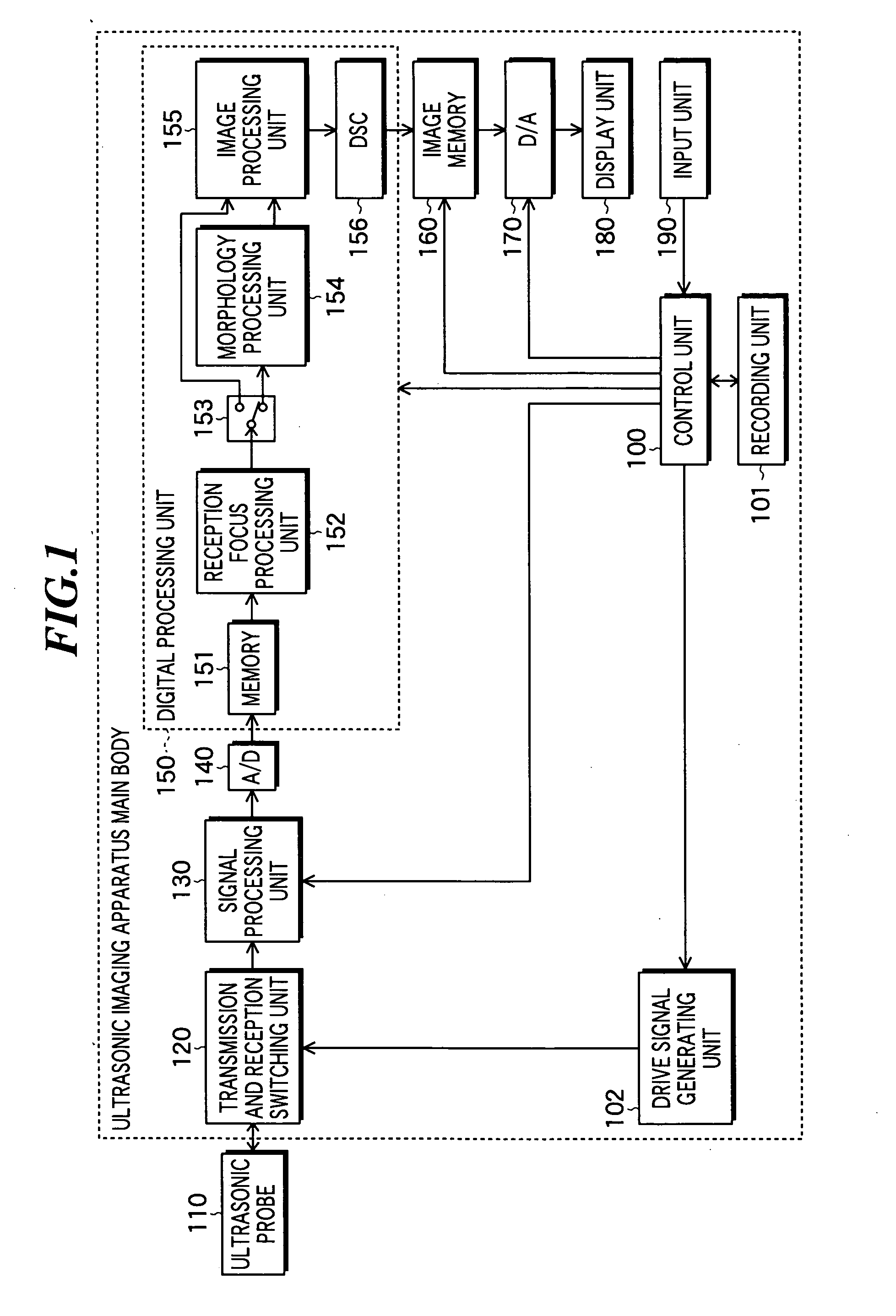
[0040]FIG. 1 is a block diagram showing the constitution of an ultrasonic imaging apparatus according to the present invention. This ultrasonic imaging apparatus includes an ultrasonic probe 110 for transmitting and receiving ultrasonic waves and an ultrasonic imaging apparatus main body for controlling the transmission and reception of ultrasonic waves and generating ultrasonic images based on acquired ultrasonic wave detection signals.

[0041] The ultrasonic probe 110 includes an ultrasonic transducer array in which plural ultrasonic transducers are arranged. Each ultrasonic transducer is fabricated by forming electrodes on both ends of a material having a piezoelectric property (piezoelectric material) such as a piezoelectric ceramic represented by PZT (Pb(lead) zirconate titanate) or a polymeric piezoelectric element represented by PVDF (polyvinylidene difluoride). when a voltage is applied to the electrodes of such an ultrasonic transducer by sending pulse electric signals or con...

second embodiment

[0079] Next, an ultrasonic imaging apparatus according to the present invention will be described. FIG. 5 is a block diagram showing the constitution of the ultrasonic imaging apparatus according to the embodiment. This ultrasonic imaging apparatus includes a digital processing unit 200 as shown in FIG. 5 in place of the digital processing unit 150 as shown in FIG. 1. Other constitution is the same as in the ultrasonic imaging apparatus as shown in FIG. 1.

[0080] The digital processing unit 200 as shown in FIG. 5 includes a frequency band division processing unit 201 in place of the morphology processing unit 154 in the digital processing unit 150 as shown in FIG. 1. The frequency band division processing unit 201 generates image data in which speckles appearing in the ultrasonic image are reduced by performing frequency enhancement on the inputted image data by using the frequency band division processing.

[0081] Next, the operation of the ultrasonic imaging apparatus as shown in FI...

third embodiment

[0097] Next, an ultrasonic imaging apparatus according to the present invention will be described. FIG. 7 is a block diagram showing the constitution of the ultrasonic imaging apparatus according to the embodiment. This ultrasonic imaging apparatus includes a digital processing unit 300 as shown in FIG. 7 in place of the digital processing unit 150 as shown in FIG. 1. Other constitution is the same as in the ultrasonic imaging apparatus as shown in FIG. 1.

[0098] The digital processing unit 300 includes a switch 301, a morphology processing unit 302, and a frequency band division processing unit 303. The functions of the memory 151, reception focus processing unit 152, image processing unit 155, and DSC 156 included in the digital processing unit 300 are the same as in the digital processing unit 150.

[0099] The switch 301 is used for switching whether speckle reduction processing is performed on the generated sound ray data or not.

[0100] The morphology processing unit 302 performs ...


PUM


Abstract

An ultrasonic image processing apparatus in which image quality of ultrasonic images can be improved by performing image processing that utilizes image characteristics of the original image. The ultrasonic image processing apparatus processes image data generated based on a signal obtained by scanning an object to be inspected by using an ultrasonic beam and respectively representing pixel values of the plurality of pixels within the ultrasonic image. The ultrasonic image processing apparatus includes a morphology processing unit for processing the image data to reduce speckles appearing in the ultrasonic image, and a DSC for converting a scan format of the image data processed by the morphology processing unit.

Description

BACKGROUND OF THE INVENTION [0001] 1. Field of the Invention [0002] The present invention relates to an ultrasonic image processing apparatus for processing ultrasonic image signals obtained by transmitting ultrasonic waves and receiving ultrasonic echoes, an ultrasonic image processing method to be used therein, and an ultrasonic image processing program for allowing a CPU to execute such ultrasonic image processing. [0003] 2. Description of a Related Art [0004] In medical fields, various imaging technologies have been developed in order to observe the interior of an object to be inspected and to make diagnoses. Especially, ultrasonic imaging for obtaining interior information of the object by transmitting and receiving ultrasonic waves enables image observation in real time and provides no exposure to radiation unlike other medical image technologies such as X-ray photography or RI (radio isotope) scintillation camera. Accordingly, ultrasonic imaging is utilized as an imaging tech...

Claims


Application Information

Patent Timeline
Patent Type & Authority Applications(United States)
IPC IPC(8): G01S7/52G01S7/521G01S15/89G06T5/00G06T5/30
CPCG01S7/52047G01S7/52079G01S15/8909G06T2207/30004G01S15/899G06T5/001G06T5/30G01S15/8977G06T5/002G06T5/003G06T2207/10132G06T2207/20192
Inventor SATOH, YOSHIAKI
Owner FUJIFILM HLDG CORP
Why Eureka
Try Eureka