
Implant retaining device

a technology of retaining device and retaining plate, which is applied in the direction of ligaments, prostheses, osteosynthesis devices, etc., can solve the problems of progressive mechanical loosening, chronic and/or debilitating back pain, and nerves passing near the affected area may be compressed and consequently irritated

Inactive Publication Date: 2005-06-30
WARSAW ORTHOPEDIC INC
View PDF99 Cites 16 Cited by
  • Summary
  • Abstract
  • Description
  • Claims
  • Application Information

AI Technical Summary

Benefits of technology

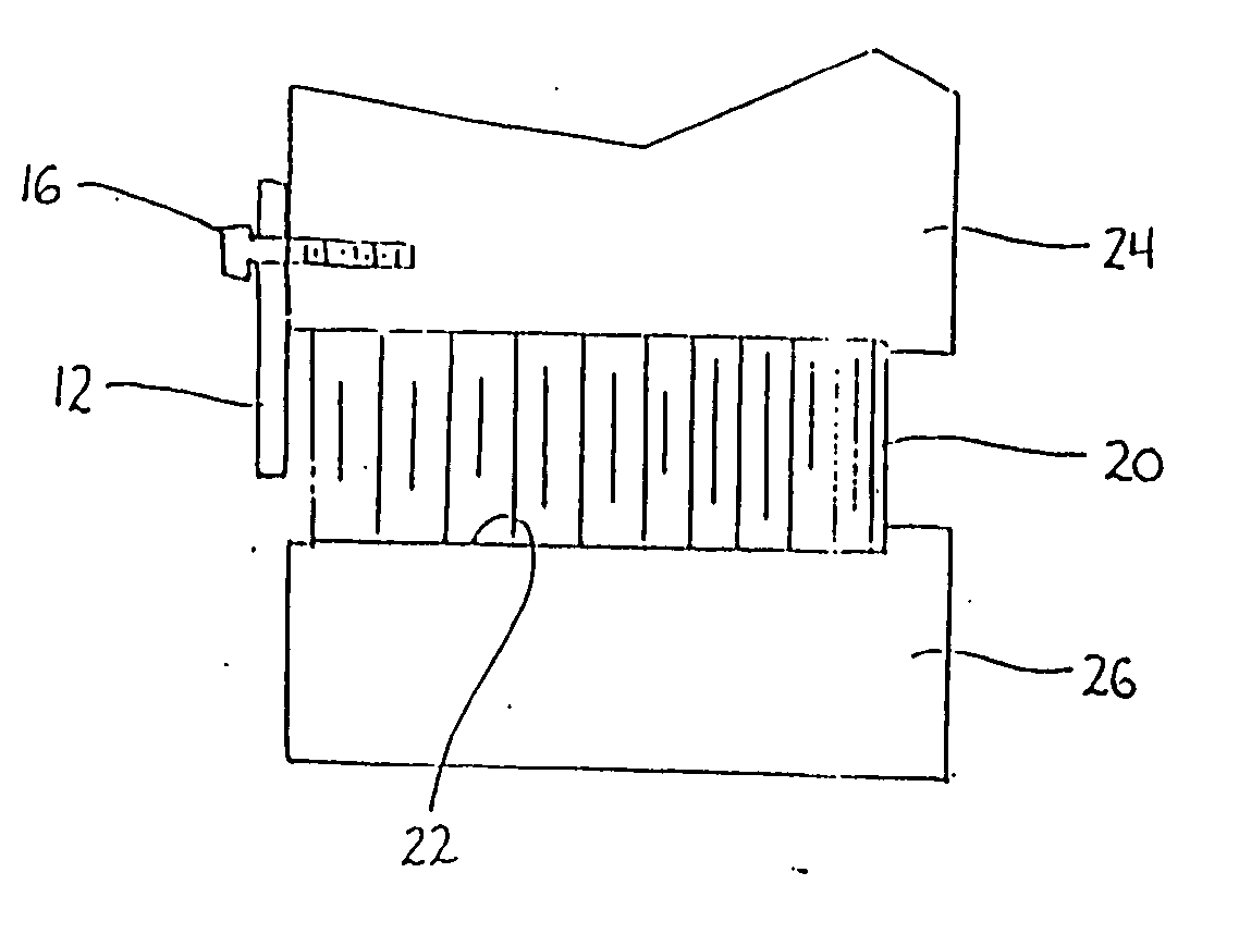
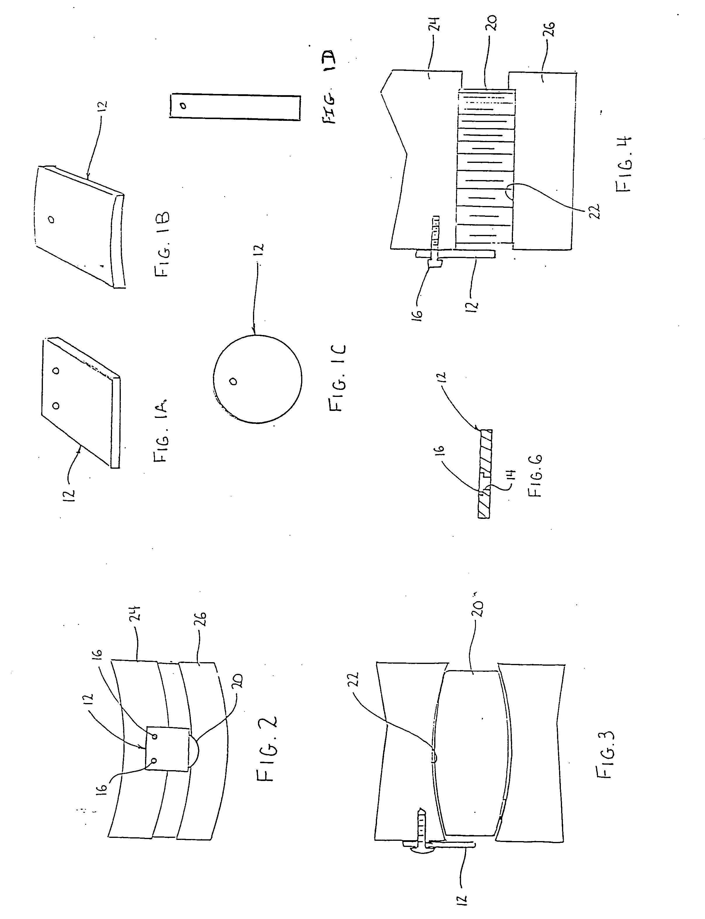
[0013] In accordance with the present disclosure, an implant retaining device is provided which prevents expulsion of an intervertebral implant from an intervertebral receiving bed. In one embodiment the implant retaining device includes a plate having at least one throughbore dimensioned to receive a screw. Single or multiple screws can be used to secure the plate to the vertebrae. The plate may have a rectangular, circular, or any other configuration capable of performing the intended function of preventing expulsion of an intervertebral implant from the receiving bed.
[0015] When the plate is formed from bone, it may be partially or fully demineralized. Partially demineralized bone provides a degree of flexibility to the plate such that it can be manipulated to conform to the surface to which it is secured, e.g., the vertebrae. Demineralization also improves the osteoconductive and osteoconductive characteristics of the plate.
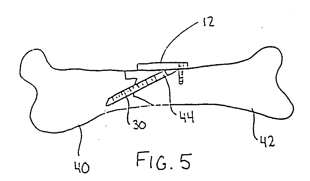
[0016] In an alternate embodiment, the plate may be used in surgical procedures other than spinal interbody fusion procedures. For example, the plate may be used during bone fracture correction procedures to prevent a bone screw from backing out of engagement with adjacent bone sections.

Problems solved by technology

When one or more disks degenerate through trauma, spondylolisthesis or other pathologies, nerves passing near the affected area may be compressed and are consequently irritated.
The result may be chronic and / or debilitating back pain.
However, the everyday activity of a patient who has undergone a spinal fusion procedure may lead to progressive mechanical loosening and eventual failure of the implant.
This significantly decreases the chances of obtaining successful fusion of the implant and the adjoining vertebrae.
Such devices often inhibit insertion of the implant into the intervertebral space.

Method used


Image

  • Implant retaining device
  • Implant retaining device
  • Implant retaining device

Examples


Embodiment Construction

[0028] Preferred embodiments of the presently disclosed implant retaining device will now be described in detail with reference to the drawings in which like reference numerals designate identical or corresponding elements in each of the several views.

[0029] The implant retaining device of the present invention is intended to be attached to at least one vertebral body, to cover at least a portion of the disk space to prevent a vertebral implant from backing out of a receiving bed. The implant retaining device is especially suited for procedures where it would be desirable to prevent an implant from backing out of the spine. However, it is entirely suitable to applications involving the repair of other bony sites in the body.

[0030] In humans, the device may be used predominately in the lumbar and thoracic regions of the spine, but, is adaptable for use in the cervical spine and other regions of the body as well.

[0031] The implant retaining device described herein may be formed of ...


PUM


Abstract

There is provided an implant retaining device, which has the effect of preventing an intervertebral implant from jutting out of the receiving bed. The implant retaining device generally includes a plate having at least one throughbore to receive a screw, and a screw for securing the plate to the vertebrae. The plate may be dimensioned to cover a portion of the opening of a receiving bed, and thus, need only be secured to a single vertebral body. In an alternate embodiment, the plate may be used during bone fracture correction procedures to prevent a bone screw from backing out of engagement with adjacent bone sections. A method of retaining an intervertebral implant using the device is also provided.

Description

CROSS REFERENCE TO RELATED APPLICATIONS [0001] This application claims priority to U.S. Provisional Application Ser. No. 60 / 242,051 filed Oct. 20, 2000, the contents of which are hereby incorporated by reference.BACKGROUND OF THE INVENTION [0002] 1. Technical Field [0003] The present disclosure is directed to an implant retaining device for preventing an implant from backing out of a receiving bed or graft site formed in body tissue. More specifically, the present disclosure is directed to an implant retaining device particularly suited for retaining an intervertebral implant in a receiving bed formed between adjacent vertebrae. [0004] 2. Background of Related Art [0005] The spine is a flexible column formed of a series of bone called vertebrae. The vertebrae are hollow and piled one upon the other, forming a strong hollow column for support of the cranium and trunk. The hollow core of the spine houses and protects the nerves of the spinal cord. The vertebrae are connected together ...

Claims


Application Information

Patent Timeline
Patent Type & Authority Applications(United States)
IPC IPC(8): A61B17/00A61B17/70A61B17/80A61B17/86A61F2/00A61F2/28A61F2/30A61F2/44
CPCA61B17/7059A61F2310/00359A61B17/86A61B2017/00831A61F2/28A61F2/30749A61F2/442A61F2/4455A61F2/446A61F2/447A61F2002/2817A61F2002/30794A61F2220/0008A61F2310/00179A61B17/80A61F2002/3079
Inventor MORRIS, JOHN W.SHIMP, LAWRENCE A.KAES, DAVID R.
Owner WARSAW ORTHOPEDIC INC
Learn More