Digital reliability monitor having autonomic repair and notification capability
a digital reliability monitor and autonomic repair technology, applied in error detection/correction, instruments, generating/distributing signals, etc., can solve problems such as difficult compensation and reliability degradation, and achieve the effect of preventing the failure of an integrated circui
- Summary
- Abstract
- Description
- Claims
- Application Information
AI Technical Summary
Benefits of technology
Problems solved by technology
Method used
Image
Examples
first embodiment
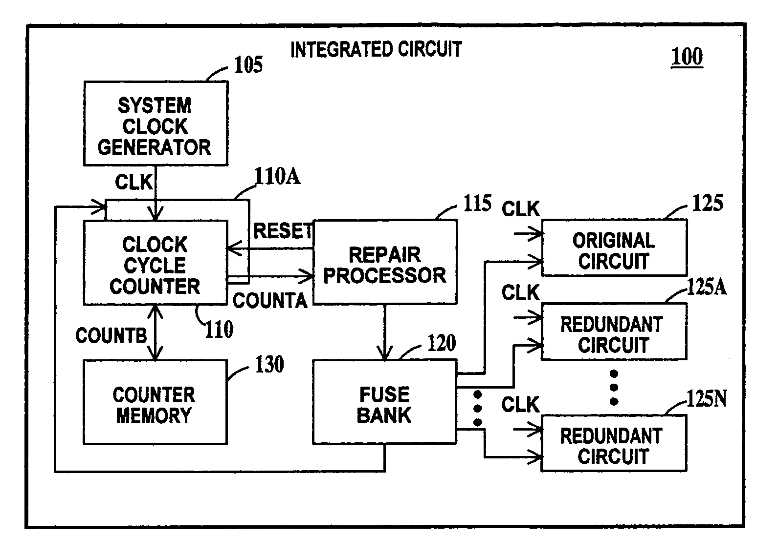
[0031]FIG. 1 is a schematic block diagram of an integrated circuit according to the present invention. In FIG. 1, an integrated circuit chip 100 includes a system clock generator 105, a clock cycle counter 110, a redundant clock cycle counter 110A, a repair processor 115, an optional fuse bank 120, an original circuit 125 and a multiple of redundant circuits 125A through 125N, each redundant circuit capable of performing the same function as the original circuit. There may be only one redundant circuit. Additionally, integrated circuit 100 may include an on-chip count memory 130 for storing the cumulated number of cycles counted by clock cycle counter 110. Alternatively, the count memory 130 may be implemented off-chip.
[0032] System clock generator (which may be a PLL circuit) generates a clock signal CLK supplied to original circuit 125 and a multiple of redundant circuits 125A through 125N and to clock cycle counter 110. Clock cycle counter 110 keeps a running tally of the number ...
second embodiment
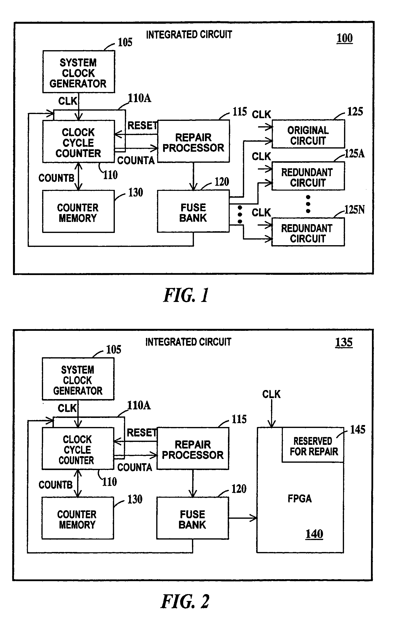
[0034] It should be noted, that clock cycle counter 110 may be repairable using the present invention. To this end, repair processor 115 can automatically insert redundant clock cycle counter 110A between system clock generator 105, memory counter 130 and the repair processor itself in place of clock cycle counter 110 when a predetermined number of clock cycles are reached. This pre-determined number of clock cycles should be significantly less than the COUNTA signal value. More than one redundant clock cycle counter may be provided and this process may be repeated as many times as there are redundant repair processors FIG. 2 is a schematic block diagram of an integrated circuit according to the present invention. In FIG. 2, integrated circuit 135 is similar to integrated circuit 100 of FIG. 1, except original circuit 125 and redundant circuits 125A through 125N of FIG. 1 are replaced with a field programmable gate array (FPGA) 140. A portion 145 of FPGA 140 is reserved for use as r...
fourth embodiment
[0054]FIG. 12 is a schematic block diagram of an integrated circuit according to the present invention. In FIG. 12, a data in signal is applied to the input of a multiplexer 500. The inputs of an original circuit 505, a multiplicity of redundant circuits 510 and a robust redundant circuit 515 are each connected to a different output of multiplexer 500. The output of original circuit 505, of redundant circuits and robust redundant circuit 515 are each connected to a different input of demultiplexer 520. The output of demultiplexer 520 is a data out signal. Multiplexer 500 and demultiplexer 520 are responsive to control signals 525A and 525B generated by a clock cycle counter and repair processor 530 that are applied respectively to the control inputs of multiplexer 500 and demultiplexer 520. Clock cycle counter and repair processor 530 receives a CLK signal.
[0055] In operation, when clock cycle counter and repair processor 530 counts a predetermined number of clock cycles, control si...
PUM
 Abstract
Description
Claims
Application Information
 - R&D
- Intellectual Property
- Life Sciences
- Materials
- Tech Scout
- Unparalleled Data Quality
- Higher Quality Content
- 60% Fewer Hallucinations
Browse by: Latest US Patents, China's latest patents, Technical Efficacy Thesaurus, Application Domain, Technology Topic, Popular Technical Reports.
© 2025 PatSnap. All rights reserved.Legal|Privacy policy|Modern Slavery Act Transparency Statement|Sitemap|About US| Contact US: help@patsnap.com


