Sensorless controller of ac motor and control method
- Summary
- Abstract
- Description
- Claims
- Application Information
AI Technical Summary
Benefits of technology
Problems solved by technology
Method used
Image

Examples
first embodiment
[0066] Next, a first embodiment according to the invention will be described with reference to the drawings.
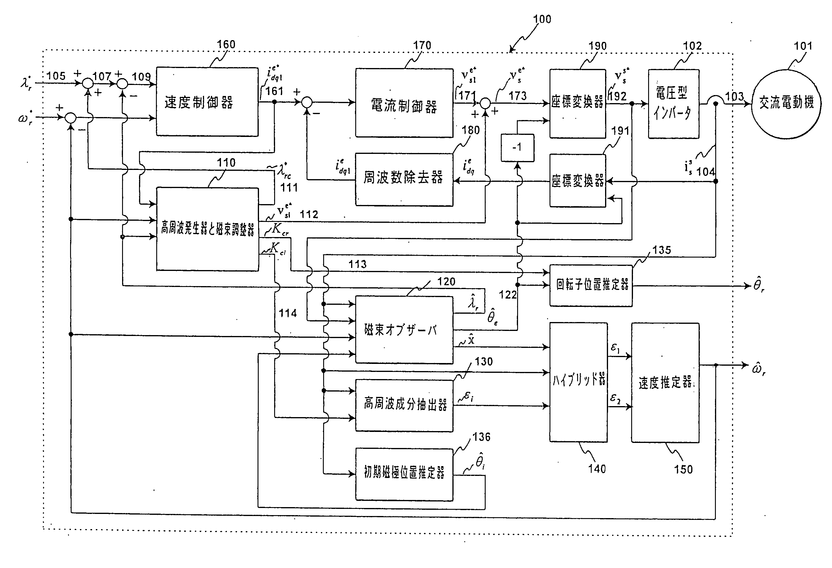
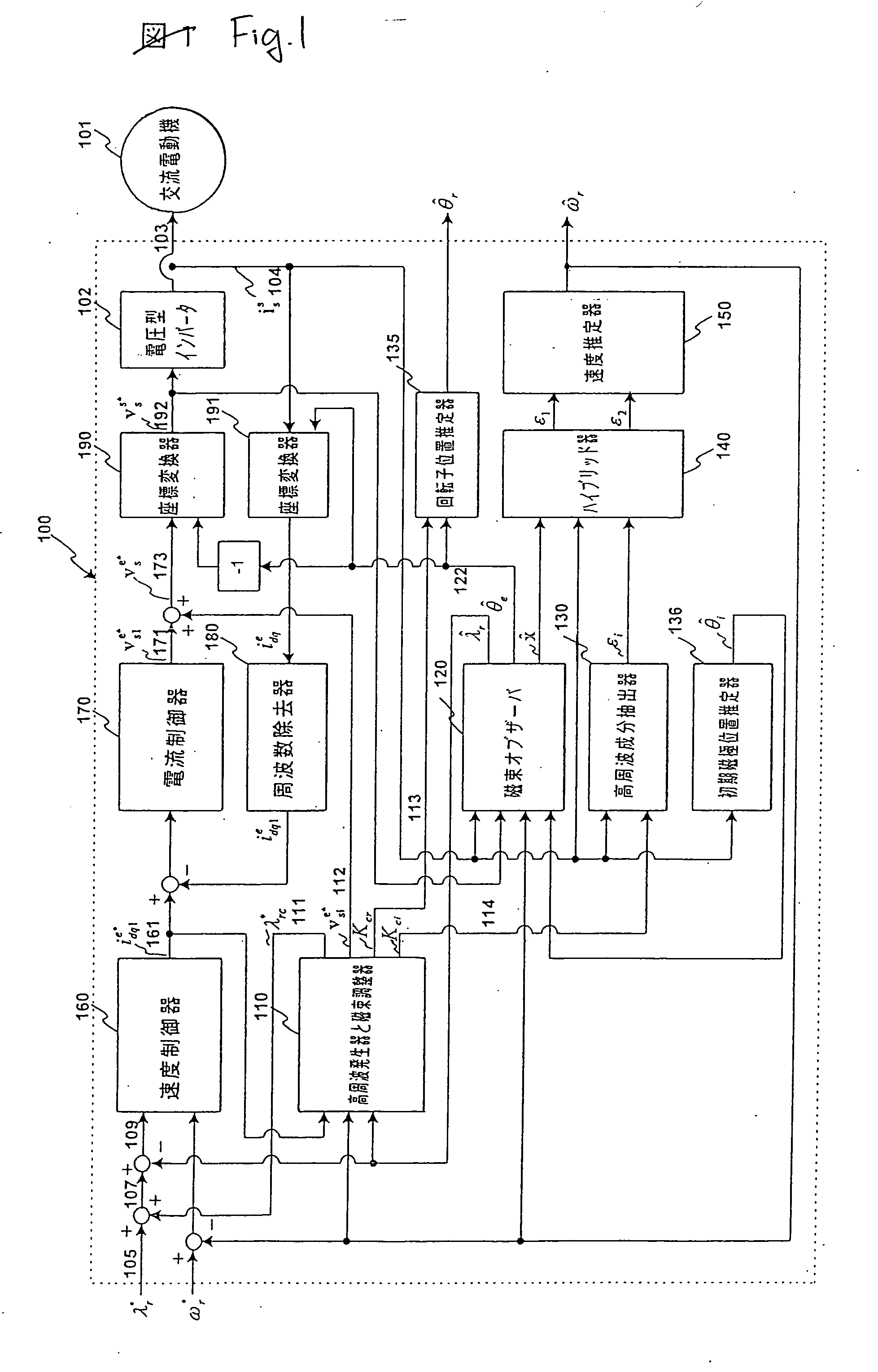
[0067]FIG. 1 is a diagram showing the structure of a sensorless control apparatus of an AC motor according to a first embodiment of the invention.
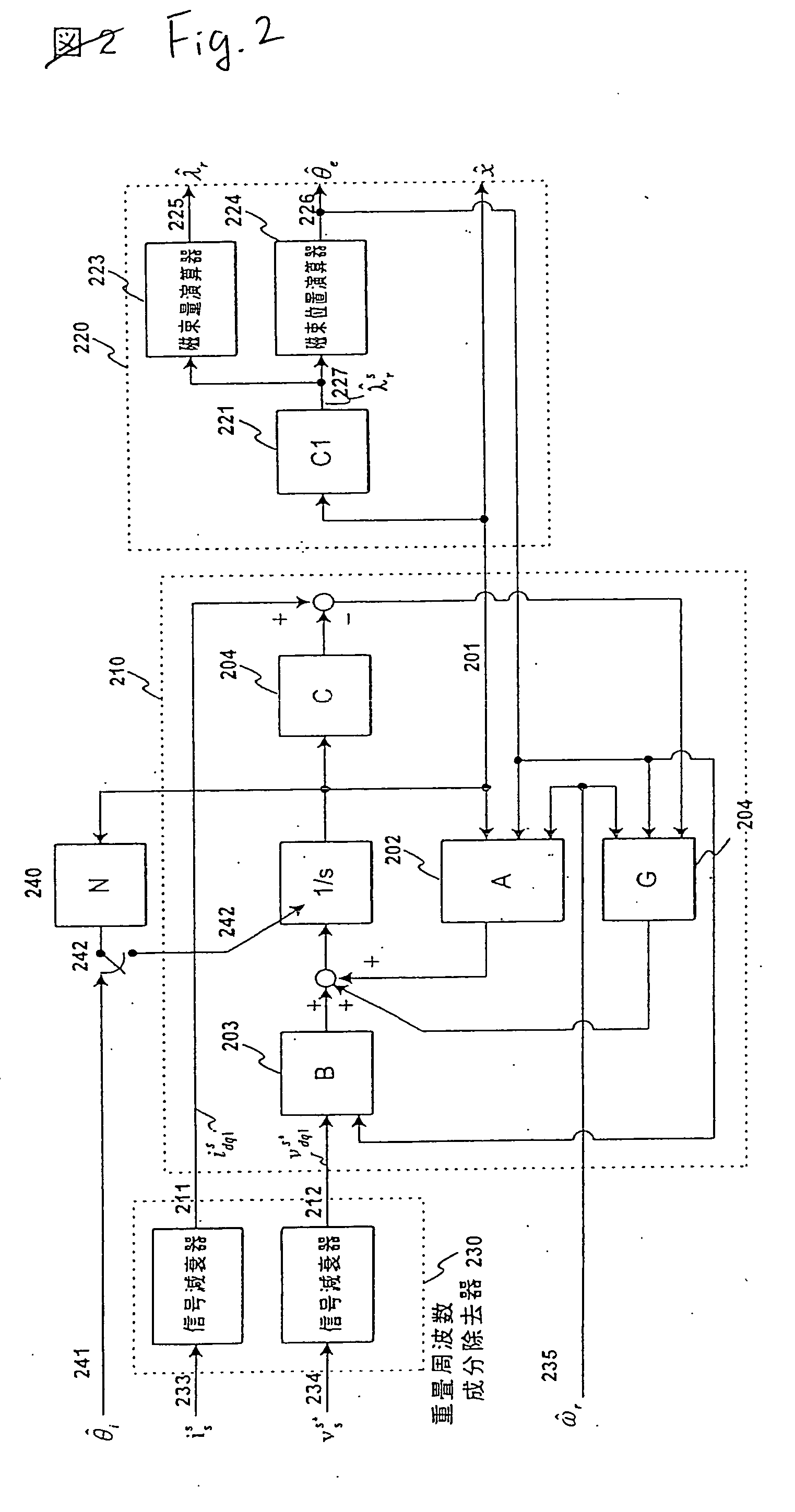
[0068]FIG. 2 is a diagram showing the details of a magnetic flux observer illustrated in FIG. 1.
[0069]FIG. 3 is a diagram showing the details of a high frequency component extractor illustrated in FIG. 1.
[0070]FIG. 4 is a diagram showing the details of a hybrid device and a speed estimator illustrated in FIG. 1.
[0071]FIG. 5 is a diagram showing the details of a high frequency generator and a magnetic flux regulator illustrated in FIG. 1.
[0072]FIG. 6 is a diagram showing a relationship between an impedance and an operation frequency in the high frequency region of the AC motor illustrated in FIG. 1.
[0073]FIG. 7 is a diagram showing a relationship between the impedance and a load in the high frequency region of the AC motor illus...
second embodiment
[0117] Next, a second embodiment according to the invention will be described with reference to the drawings.
[0118]FIG. 8 is a diagram showing the structure of a sensorless control apparatus of an AC motor according to the second embodiment of the invention.
[0119]FIG. 9 is a diagram showing the details of a high frequency component extractor illustrated in FIG. 8.
[0120]FIG. 10 is a diagram showing the details of a high frequency generator and a magnetic flux regulator illustrated in FIG. 8.
[0121]FIG. 11 is a chart showing the characteristic of a double harmonic in the case in which a voltage high frequency is superposed in an initial magnetic pole estimator illustrated in FIG. 8.
[0122]FIG. 12 is an explanatory diagram showing the initial magnetic pole estimator illustrated in FIGS. 1 and 8.
[0123]FIG. 8 is a diagram showing the structure of a sensorless control apparatus of an AC motor according to the second embodiment of the invention, illustrating a method for superposing a h...
third embodiment
[0144] Next, a third embodiment according to the invention will be described with reference to the drawings.
[0145]FIG. 13 is a diagram showing the structure of a sensorless control apparatus of an AC motor according to the third embodiment of the invention.
[0146]FIG. 14 is a diagram showing the details of a magnetic flux observer illustrated in FIG. 13.
[0147]FIG. 15 is a diagram showing the details of a hybrid device and a speed estimator illustrated in FIG. 13.
[0148]FIG. 16 is a diagram showing the details of a high frequency generator and magnetic flux regulator illustrated in FIG. 13.
[0149] While the example of the AC motor (synchronous motor) has been described in the above embodiments, an induction motor will be described in the embodiment. A control block shown in FIG. 13 can be implemented through a digital operation in order to drive an AC motor (induction motor) 101 in the same manner as in FIG. 1 by using a voltage type inverter 102. Moreover, the same control block ca...
PUM
 Abstract
Description
Claims
Application Information
 - Generate Ideas
- Intellectual Property
- Life Sciences
- Materials
- Tech Scout
- Unparalleled Data Quality
- Higher Quality Content
- 60% Fewer Hallucinations
Browse by: Latest US Patents, China's latest patents, Technical Efficacy Thesaurus, Application Domain, Technology Topic, Popular Technical Reports.
© 2025 PatSnap. All rights reserved.Legal|Privacy policy|Modern Slavery Act Transparency Statement|Sitemap|About US| Contact US: help@patsnap.com