Ultra wideband bow-tie printed antenna

a printed antenna and ultra wideband technology, applied in the direction of antennas, antenna details, antenna feed intermediates, etc., can solve the problems of not being able to not being able to cover the ultra wideband frequency range of 3.1-10.6 ghz, and printing antennas that cannot meet the practical use of ultra wideband communication devices, etc., to achieve the effect of easy fabrication and light weigh

Inactive Publication Date: 2005-07-07
NAT INST OF INFORMATION & COMM TECH
View PDF7 Cites 18 Cited by
  • Summary
  • Abstract
  • Description
  • Claims
  • Application Information

AI Technical Summary

Benefits of technology

[0016] The present invention has as an object to provide an ultra wideband printed antenna, which is small in profile and light weight and has wide potential use for UWB portable wireless devices. The present invention relates to a printed antenna that is a new type of dipole antenna, which has impedance matching portion connected to strip lines and covers the ultra wide frequency band range. The dipole antenna is printed on a dielectric substrate, so that it is small profile, light weight, easy to fabricate and low cost.
[0018] The VSWR characteristic of the antenna according to aspects of the present invention is under 3 in a frequency range from 3.1 GHz to 10.6 GHz, and the other frequency characteristic, like gain, etc. is good in the range of a wide frequency of 3.1 GHz to 10.6 GHz, and is an omni-direction pattern in the frequency range. Because of these features, the ultra wideband antenna of the present invention can be used for devices of an ultra wideband communication system from 3.01 GHz to 10.6 GHz. The antenna profile, moreover, is a very small size, such as a length of 16 mm, a width of 40 mm, and a thickness of 0.5 mm, very light weight, easy to fabricate and low-cost. The present invention has as further object to create a fine effect for practical use and its fabrication.

Problems solved by technology

The prior art of a printed bow-tie type antenna shown in FIG. 14A and FIG. 14B does not have the wide frequency range such as the ultra wide frequency, thus it is unsuitable to cover the ultra wideband frequency range.
Their frequency range, however, is not be able to cover the ultra wideband communication frequency range of 3.1-10.6 GHz.
As mentioned above the prior art printed antenna have not satisfied the practical use of the ultra wideband communication devices so far.
Because it is very difficult to make the wideband printed antenna having good frequency characteristics of the ultra wideband communication.

Method used


Image

  • Ultra wideband bow-tie printed antenna
  • Ultra wideband bow-tie printed antenna
  • Ultra wideband bow-tie printed antenna

Examples


Embodiment Construction

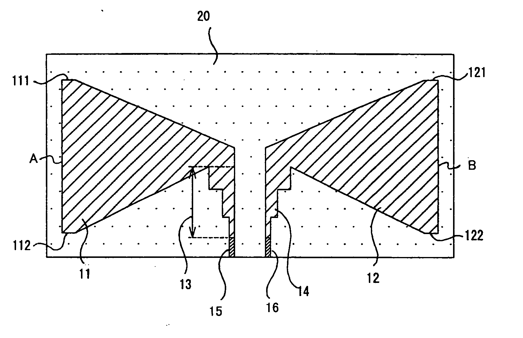
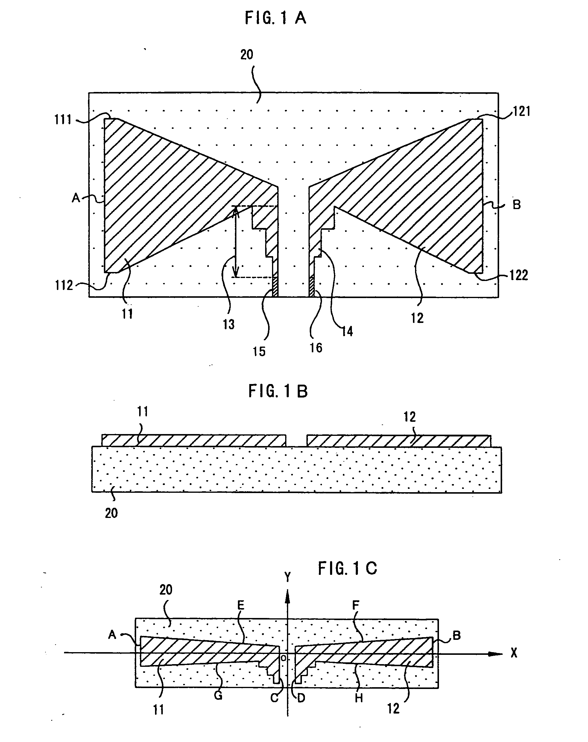
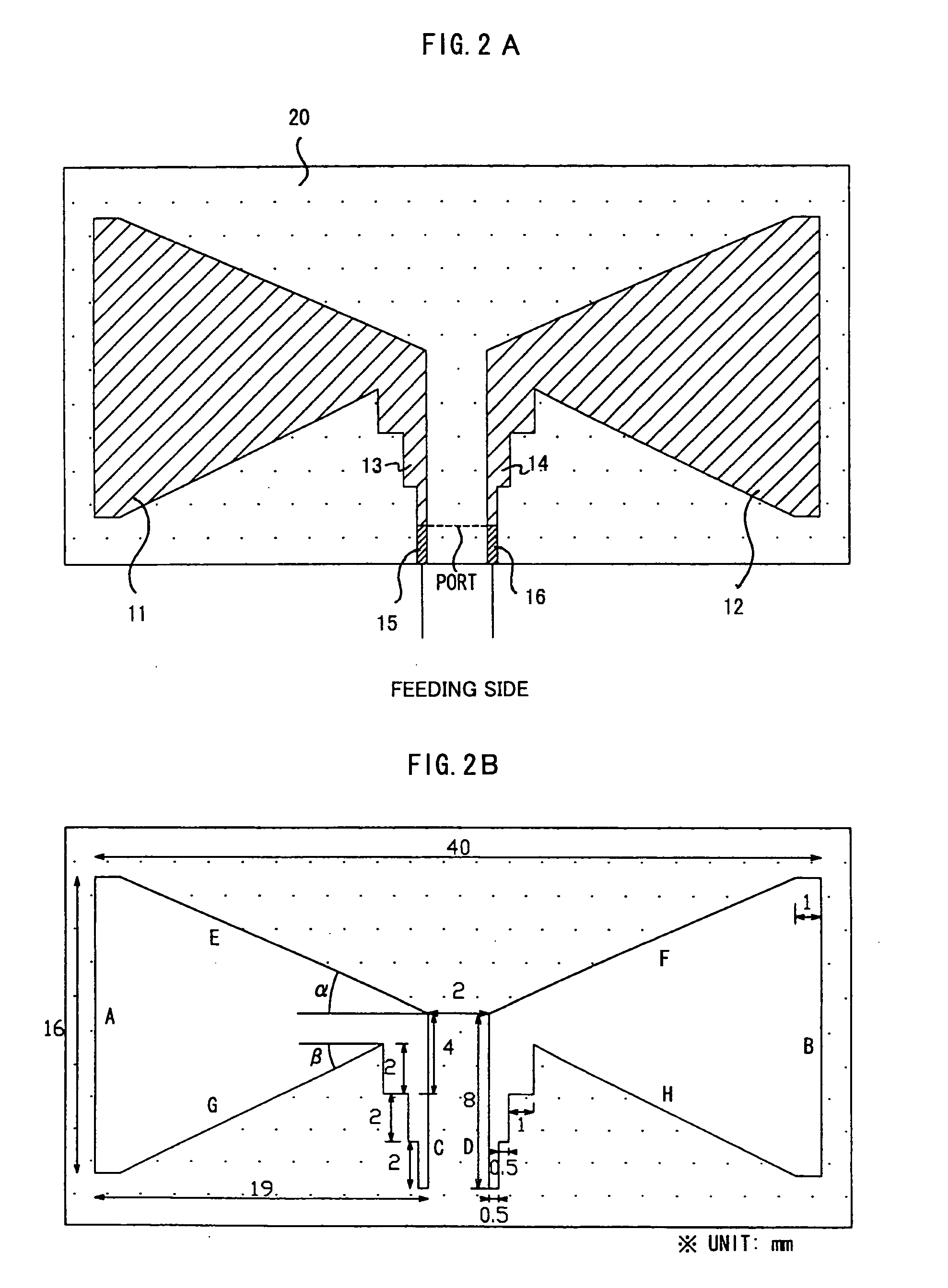
[0042]FIG. 1A and FIG. 1B show an ultra wideband printed antenna according to a preferred embodiment of the present invention. Each of antenna elements 11, 12 is the same size, and a pair of the antenna elements makes a bow-tie shape. They are printed on a thin substrate of 0.5 mm made with the relative permittivity of εr=4.4. The printed antenna according to the preferred embodiment of the present invention is a kind of dipole antenna, which is different from the bow-tie type patch antenna shown in FIG. 14A and FIG. 14B. Moreover impedance matching portions are formed between the antenna elements and strip lines. The printed antenna according to the preferred embodiment of the present invention is fed through a co-planar strip line of 75 Ω for example.

[0043] In the following embodiment, substrate 20 is made of FR4, and the printed pattern comprising antenna elements 11, 12 and impedance matching parts 13, 14 are made of copper. Insulation materials, such as Silicon (Si) or Teflon,...


PUM


Abstract

A printed antenna includes a dielectric substrate having a pair of printed antenna elements to form a dipole antenna. On an antenna plane, an xy axis system is defined so that an origin is defined at a center of location of the antenna elements, and an x axis is set in a direction that the antenna elements are arranged, a y axis is set in the direction perpendicular to the x axis, and a size of the antenna elements in the direction of the y axis become gradually larger according to the x axis changing in an outer direction. Each of the antenna elements has an impedance matching part at a feeding side of the antenna elements. The printed antenna can be used in an ultra wide-band frequency, and is small profile, is light weight and low in cost.

Description

CROSS-REFERENCE TO RELATED APPLICATIONS [0001] This application claims priority to Japanese Patent Application No. 2003-317160, filed Sep. 9, 2003 in Japan, the contents of which are incorporated herein by reference. BACKGROUND OF THE INVENTION [0002] 1. Field of the Invention [0003] The present invention relates to a printed antenna, which has an ultra wide-band (“UWB”) frequency range. The ultra wideband antenna is loaded on UWB wireless devices for its use. Therefore, it is required to be low and small profile, light weight and low cost. Moreover, the characteristics of ultra wideband antenna have to be constant gain and omni-directional patterns. [0004] 2. Description of the Related Art [0005] Growing use of wireless communication devices has forced the need of large bandwidth, and large bit-rates, such as bit-rates of several hundred Mbps. It requires an antenna having excellent characteristics in the range of ultra wideband frequency. Further the antenna has to be small profil...

Claims


Application Information

Patent Timeline
Patent Type & Authority Applications(United States)
IPC IPC(8): H01Q9/28H01Q1/38
CPCH01Q9/285
Inventor YAZDANDOOST, KAMYA YEKEHKOHNO, RYUJI
Owner NAT INST OF INFORMATION & COMM TECH
Why Eureka
Try Eureka