Recording condition setting method and information recorder using same
- Summary
- Abstract
- Description
- Claims
- Application Information
AI Technical Summary
Benefits of technology
Problems solved by technology
Method used
Image
Examples
example 1
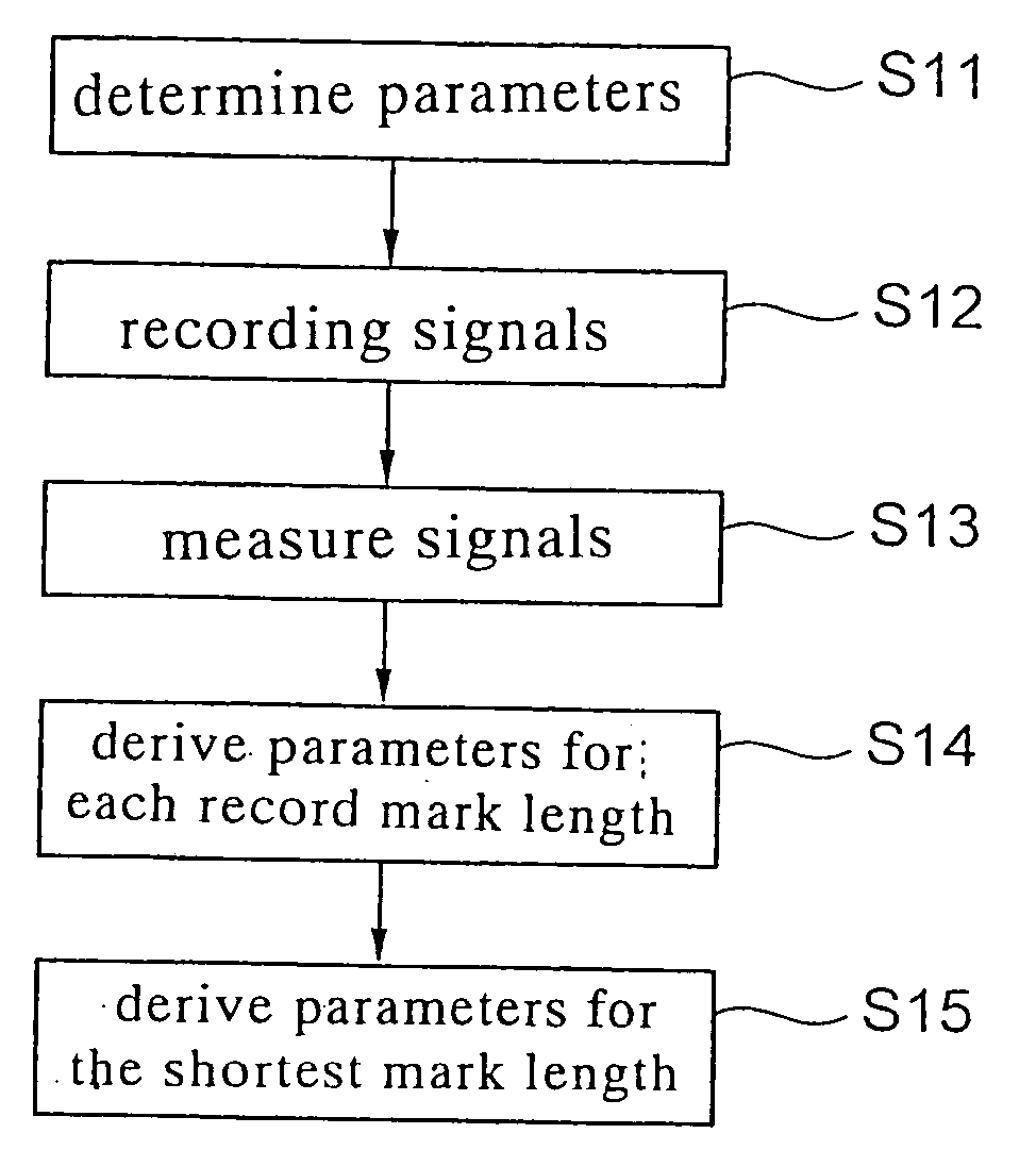
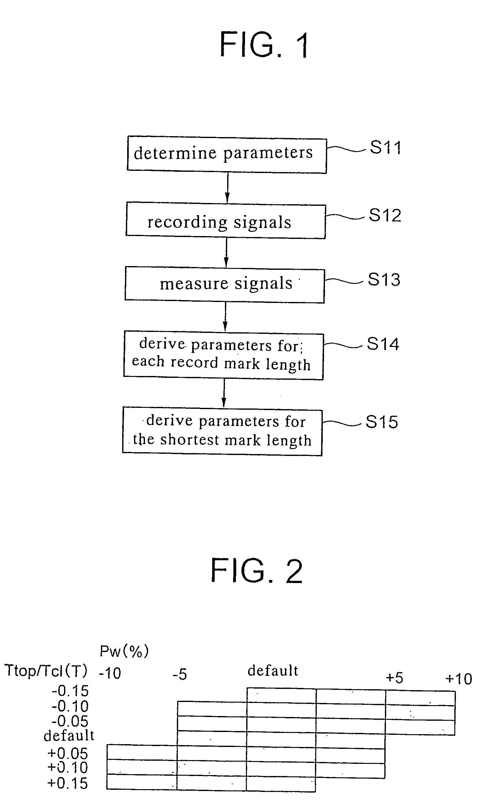
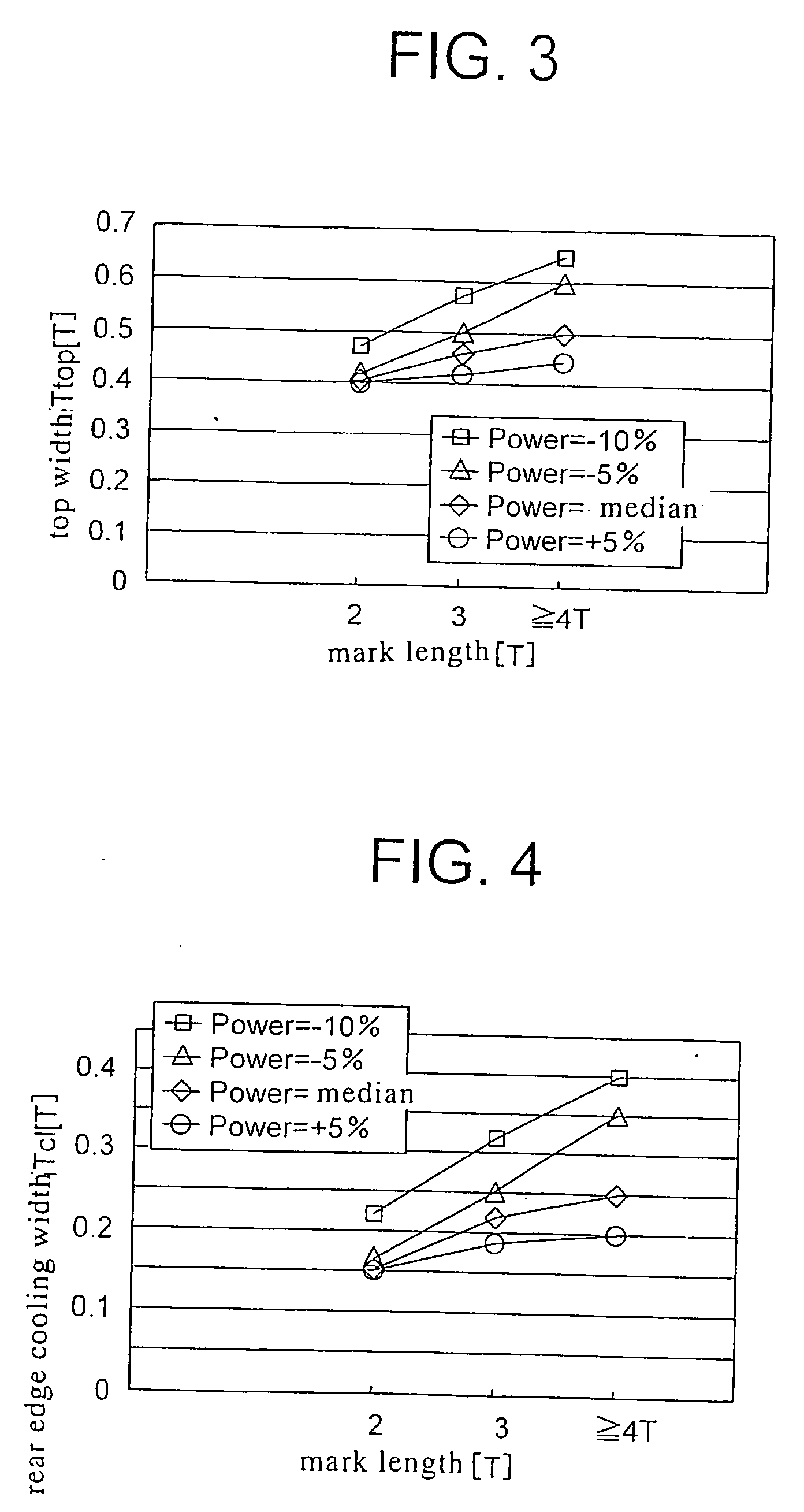
[0074] As an example, an experiment was performed while using an optical disk drive, which mounts thereon an optical head having a numerical aperture NA of 0.85 and a laser wavelength λ of 405 nm. In the experiment, the recording condition for recording on a phase-change optical disk having an overcoat layer of 0.1 mm thickness and running at a linear speed of 5 m / s, with the shortest mark for the (1,7) RLL encoding scheme being set at 0.13 μm (the shortest bit length corresponding to 0.104 μm / bit) was determined based on the procedure shown in FIG. 1. The (n−1)-pulse train shown in FIG. 17B was used as the driving waveform of the laser for forming the record mark on the optical disk. In the optical disk drive, each of the parameters other than the recording power Pw, top width Ttop and rear edge cooling width Tcl was set at the default read from the optical disk itself in step S1 (FIG. 1).
[0075]FIG. 2 exemplifies combinations of changes in the recording condition. In step S12 (FIG...
example 2
[0090] As an example, an experiment was performed using an optical disk drive mounting thereon an optical head having a numerical aperture NA of 0.65 and a laser wavelength λ of 405 nm. In the experiment, the recording condition for recording on a phase-change optical disk having an overcoat layer of 0.6 mm thickness, with the 2T shortest mark length (Lmin) for the (1,7) RLL encoding scheme being set at 0.125 μm, was determined based on the procedure shown in FIG. 5. The ratio between the amplitude of the signal reproduced from the longest mark and the amplitude of the signal reproduced from the shortest mark upon setting the 2T shortest mark length at 0.125 μm was not more than 10% and the jitter of the reproduced signal including the signal reproduced from the shortest mark exceeded 15%, whereby it was impossible to determine the parameters etc. of the recording strategy directly by using the reproduced signal.
[0091] In the experiment, the (n−1)-pulse train shown in FIG. 17B was ...
PUM
 Abstract
Description
Claims
Application Information
 - R&D
- Intellectual Property
- Life Sciences
- Materials
- Tech Scout
- Unparalleled Data Quality
- Higher Quality Content
- 60% Fewer Hallucinations
Browse by: Latest US Patents, China's latest patents, Technical Efficacy Thesaurus, Application Domain, Technology Topic, Popular Technical Reports.
© 2025 PatSnap. All rights reserved.Legal|Privacy policy|Modern Slavery Act Transparency Statement|Sitemap|About US| Contact US: help@patsnap.com


