Surgical retractor having low-friction actuating means and contoured blade arms

a technology of actuating means and blade arms, applied in the field of surgical retractors, can solve the problems of high friction in the retractor system, high generate high loads, and achieve the effects of reducing separation force and torque, facilitating its deployment, and more uniform loads

Inactive Publication Date: 2005-07-07
PAOLITTO ANTHONY +2
View PDF15 Cites 21 Cited by
  • Summary
  • Abstract
  • Description
  • Claims
  • Application Information

AI Technical Summary

Benefits of technology

[0037] The retractor according to the present invention seeks to reduce the separating force and torque which the surgeon must apply at the driving member of the retractor and thereby tends to facilitate its deployment. As well, the retractor of the present invention attempts to substantially normalize retraction loads; that is, it is intended to allow the surgeon to sense more uniform loads and to thereby result in a steadier deployment of the retractor throughout its open range. Since a jerky deployment of the retractor can lead to sudden retraction movements, normalization may result in less risk of inadvertent tissue trauma or sternum fracture. Thus the present invention describes a low-friction interfacing member for providing load reduction and load normalization in thoracic retractors.
[0038] In surgical interventions which obtain access to the coronary organs via a midline sternotomy incision, the nature of the surgical incision is substantially linear since the sternum or breastbone is cut in two. The patient's thoracic structure usually imposes the greatest resistance to retraction at the extremities of the surgical incision, where tearing of tissue most often occurs. This also tends to result in the highest concentration of resistance load being applied to the retractor arms at the free ends thereof, namely at the extremity of the incision location which is furthest away from the rack and pinion mechanism of the retractor. The retractor of this invention, with its arcuate spreader arms and contoured thoracic structure engaging members is expected to reduce these concentrated loads at the incision extremities for a desired retracted opening in the thoracic structure at the mid length location along the surgical incision. This would therefore be advantageous since the overall separating force the surgeon must apply will also be reduced for a given opening in the thoracic structure.
[0039] In retracting a patient's thoracic structure subsequent to a midline sternotomy, the two halves of the ribcage do not have a tendency to spread apart in a parallel orientation along the sternotomy incision. The top portion of the ribcage tends to go from a generally cylindrical-shaped surface, when the incision is not retracted, to a generally barrel-shaped surface when the incision is retracted. That is, the center portion of the ribcage along the sternotomy incision retracts more readily in an outward and upward direction than the extremities of the incision, which are somewhat restricted by the endpoints thereof at the patient's abdomen and collarbone. This forms a lens-shaped opening for the retracted incision. Many prior art retractors do not accommodate this barrelling behaviour. The retractor of this invention, with its contoured thoracic structure engaging members that interface with the two halves of the patient's incised sternum and that conform closely to this non-parallel barrelling of the ribcage halves along the sternotomy incision during retraction, would offer advantages in tending to minimize the likelihood of sternal breakages and induced tissue trauma.

Problems solved by technology

The separating force to overcome the resistance load on the retractor may at times be excessive since: a patient may be very corpulent; a patient's bones may be very brittle, and therefore especially resistant to rotation of the ribs about the spine; the retractor blade design may result in concentrated loads being generated at locations remote from the rack bar and pinion mechanism; friction in the retractor system may be high; and wear may have occurred at the mechanical interface between moving components.
This results in a substantially stable orientation when both pins are engaged with the rack teeth, and a substantially unstable orientation when only one pin is engaged with a rack tooth.
This also results in an alternation of discrete and substantially stable locked positions with unstable unlocked positions of the retractor arms along the entire length of the rack.

Method used


Image

  • Surgical retractor having low-friction actuating means and contoured blade arms
  • Surgical retractor having low-friction actuating means and contoured blade arms
  • Surgical retractor having low-friction actuating means and contoured blade arms

Examples


first embodiment

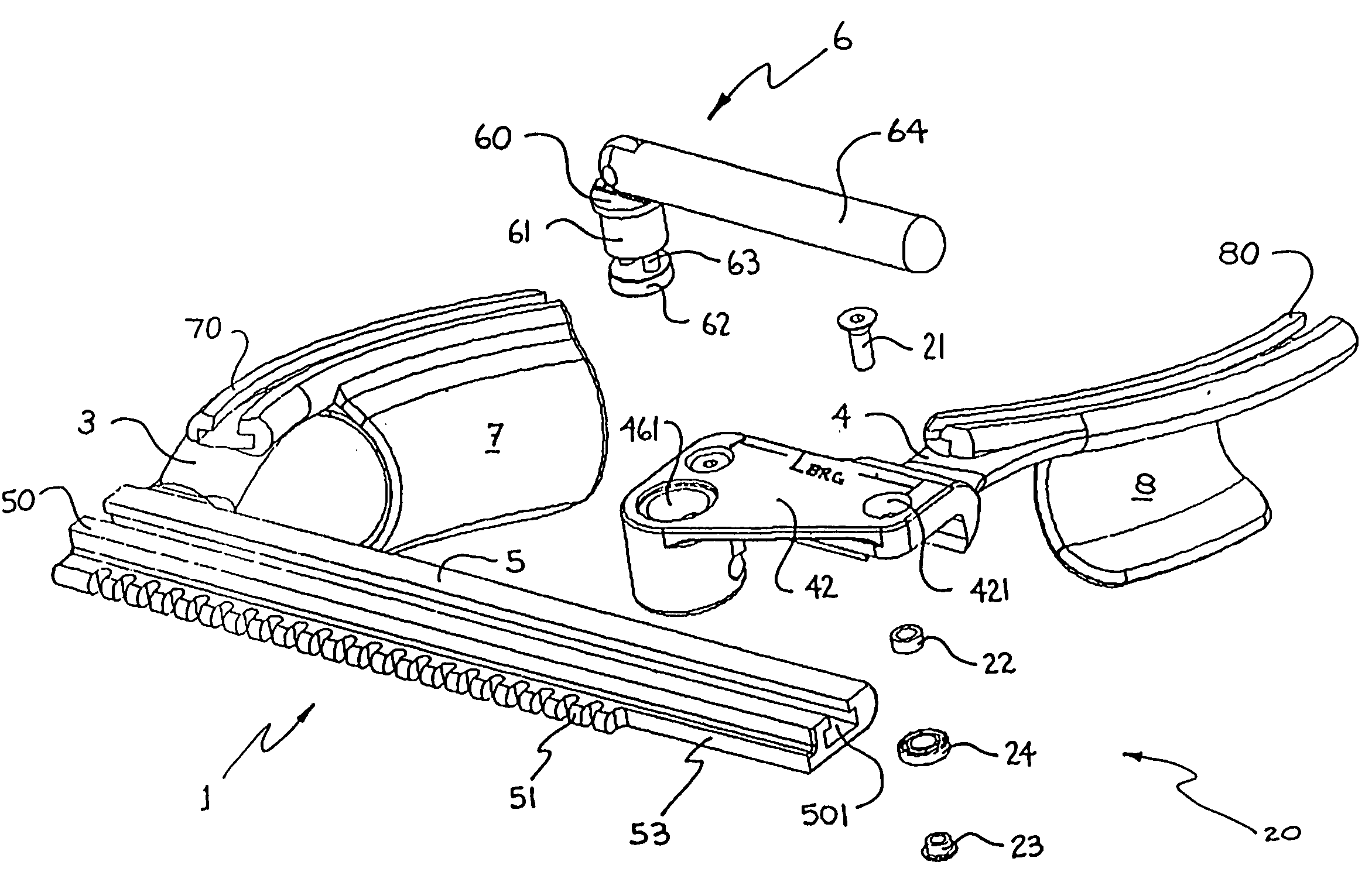
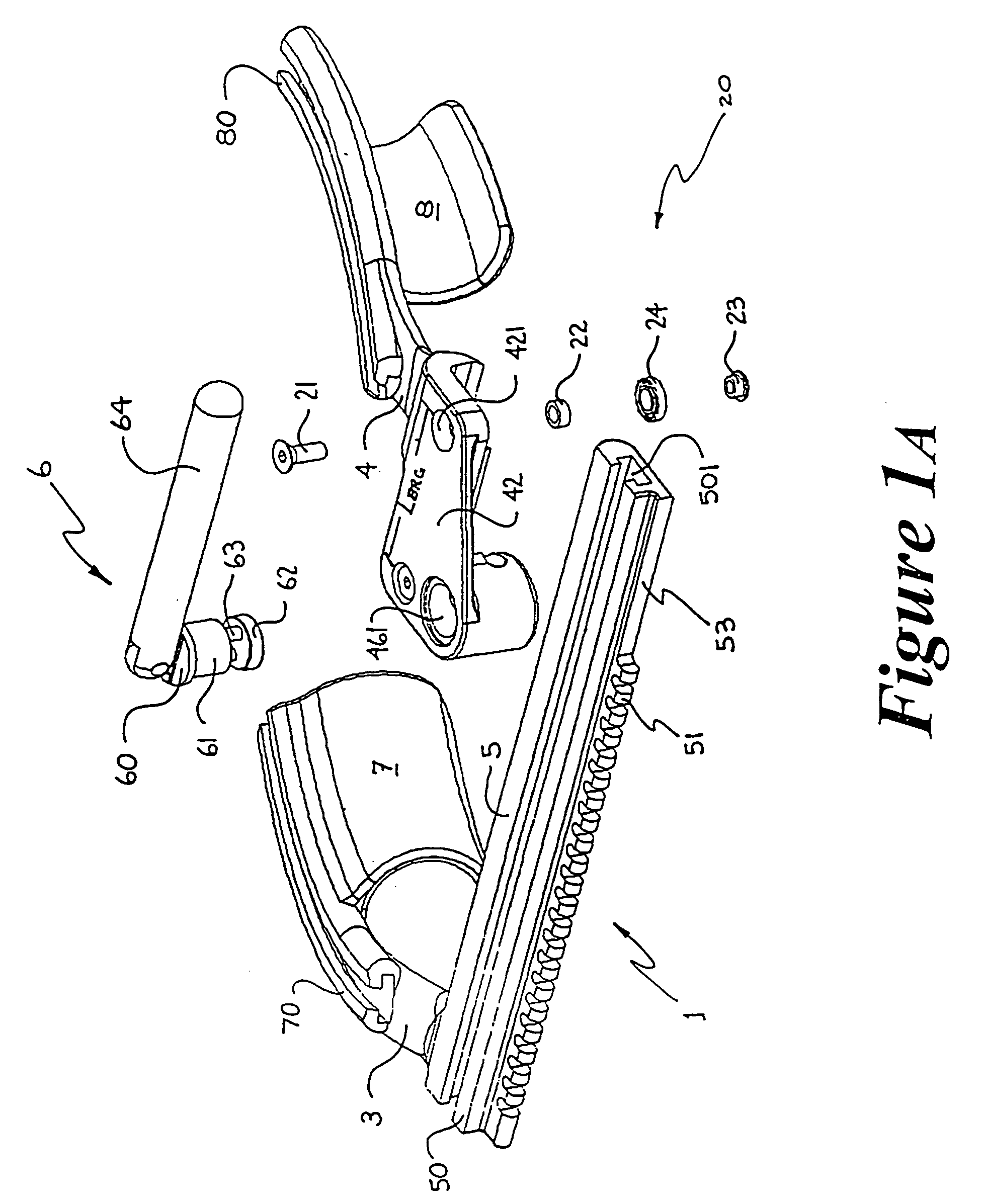
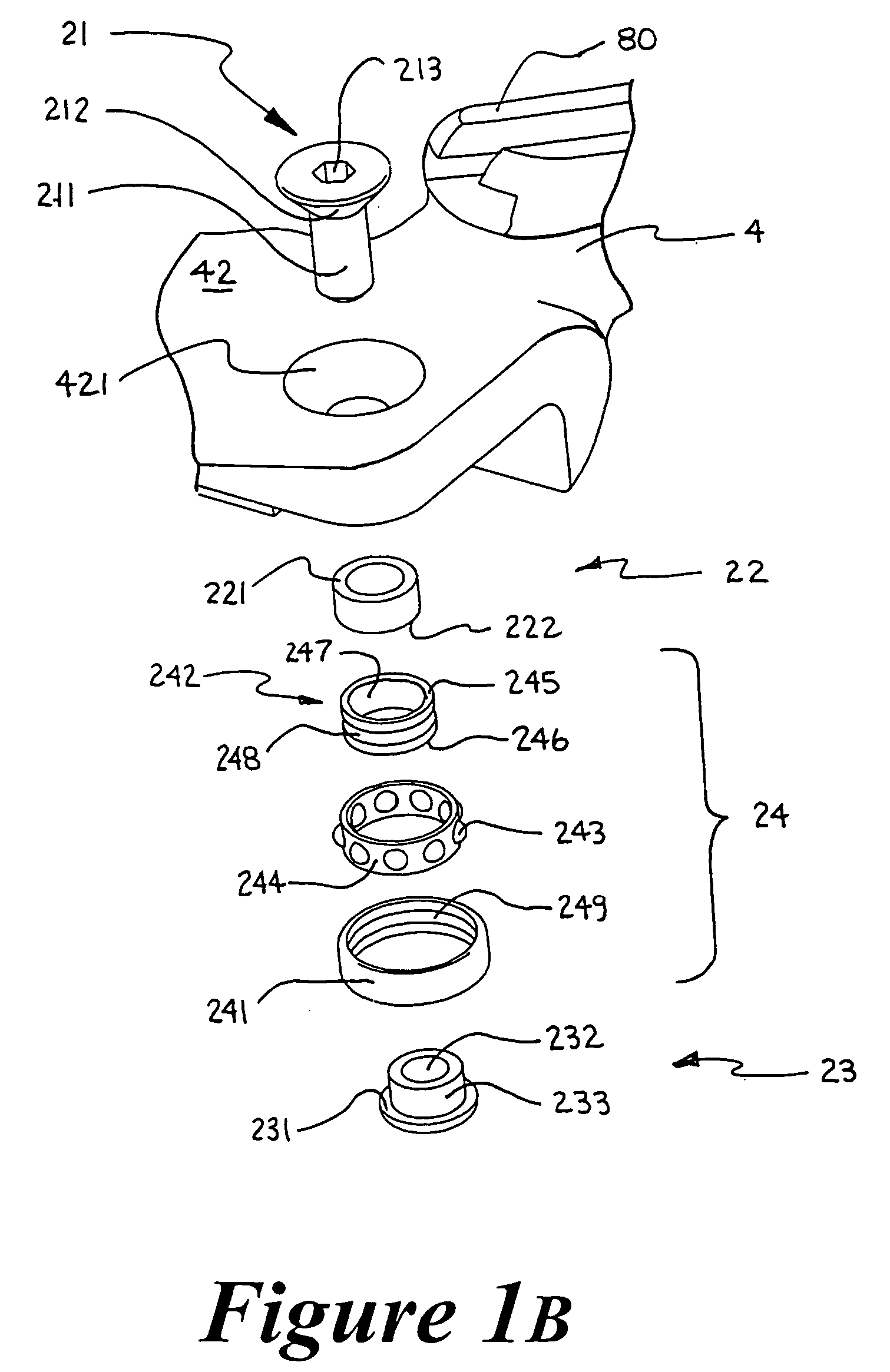
[0097] Although the first embodiment, as illustrated in FIGS. 1A, 1B and 3, employs an open configuration ball bearing 24 as part of the load-reducing and load-normalizing mechanism 20, other rolling-element-type bearings can also be employed to configure alternative embodiments for the load-reducing and load-normalizing mechanism. FIGS. 4A to 4I illustrate the top cross-sectional half of rolling-element-type bearing variants, about their respective centerlines CL. Suitable bearings may include but are not limited to: (4A) open configuration ball bearing (also the illustrated example in FIG. 1A); (4B) shielded ball bearing; (4C) sealed ball bearing; (4D) external self-aligning ball bearing; (4E) double row ball bearing; (4F) self-aligning ball bearing; (4G) straight roller bearing; (4H) needle bearing; and (4I) tapered roller bearing. In these figures, the bearing outer race is generically referred to as OR, the inner race as IR, and the complement of rolling elements as RE. FIG. 4J...

third embodiment

[0112] In this third embodiment, feature 423 covered by sliding member 25 forms a T-shaped key which slides within a T-shaped keyseat slot 501 in the rack bar 5. Other variations of key and keyslot geometry are possible which do not depart from the spirit of this invention, such as: L-shape, dovetail, firtree and others apparent to those skilled in this art.

fourth embodiment

[0113]FIG. 8 illustrates a fourth embodiment according to the present invention. In order to reduce the friction force FfPINION, and consequently the force FSURGEON and torque MSURGEON the surgeon must apply at the crank handle 641, a friction-reducing member 631 is introduced as part of the pinion mechanism 16.

[0114] In a first configuration of this fourth embodiment, feature 631 is a substantially cylindrical sleeve which is press-fit (interference fit) onto pinion member 632. With the rotation of the crank 641, the outer surface of sleeve feature 631 rotates as it slides relative to the rack tooth 511 surface. The material of the sleeve is either teflon, plastic, polymer, or any other material well-suited to provide substantially frictionless movement of the pinion relative to the rack. The sleeve tends not only to reduce friction between the pinion member 632 and the rack tooth 511, but also to reduce the wear at this interface. In most prior art retractors, the pinion member an...


PUM


Abstract

A retractor for performing surgery, for instance cardiac surgery on the coronary organs of a patient, which has a driving member to which the surgeon input is applied in the form of a mechanical force or torque, a thoracic structure engaging member which interfaces and retracts the patient's thoracic structure when surgeon input is applied to the movable driving member, and a surgeon input load-reducing and load-normalizing mechanism provided in at least one mechanical interface between retractor components where relative motion therebetween occurs. The load-reducing and load-normalizing mechanisms are preferably non-lubricated, thereby tending to ensure an inert and sterile environment during surgery. The retractor is comprised of a locking arrangement allowing a retractor spreader arm to be secured at any longitudinal position along the rack bar, independently of the pinion's position. The thoracic retractor according to this invention tends to improve the efficiency and safety of surgery by reducing the surgeon input required to achieve retraction, and by allowing said input to be applied more uniformly and in a controlled manner free from sudden movements through the normalization of retractor variables.

Description

FIELD OF THE INVENTION [0001] The present invention relates to the field of surgical apparatus and more specifically, to retractors used in surgery. BACKGROUND OF THE INVENTION [0002] Retractors of all shapes and sizes have been present since the dawn of surgery. A common type of retractor is the chest retractor or thoracic retractor. Retractors of this category may comprise sternum retractors, thoracotomy retractors, mini-thoracotomy retractors, mini-sternotomy retractors, and retractors used for the surgical harvesting of internal thoracic arteries through a sternotomy or intercostal approach incision. For instance, such internal thoracic arteries may comprise the left internal mammary artery. [0003] Sternum retractors are commonly used in cardiac surgery. Cardiac surgery may take several forms. For instance, these forms include traditional coronary artery bypass graft surgery (CABG) requiring the heart-lung machine, CABG surgery performed directly on a beating heart, minimally in...

Claims


Application Information

Patent Timeline
Patent Type & Authority Applications(United States)
IPC IPC(8): A61B17/00A61B17/02
CPCA61B2017/0084A61B17/0206
Inventor PAOLITTO, ANTHONYVALENTINI, VALERIOCARTIER, RAYMOND
Owner PAOLITTO ANTHONY
Why Eureka
Try Eureka