
Tube for medical applications and circuit incorporating such tube

a technology of medical applications and tubes, applied in the direction of prosthesis, catheters, other blood circulation devices, etc., can solve the problems of incineration, waste of resources, and waste of resources, and achieve the effect of simple and economic manufactur

Inactive Publication Date: 2005-07-07
GAMBRO LUNDIA AB
View PDF16 Cites 12 Cited by
  • Summary
  • Abstract
  • Description
  • Claims
  • Application Information

AI Technical Summary

Benefits of technology

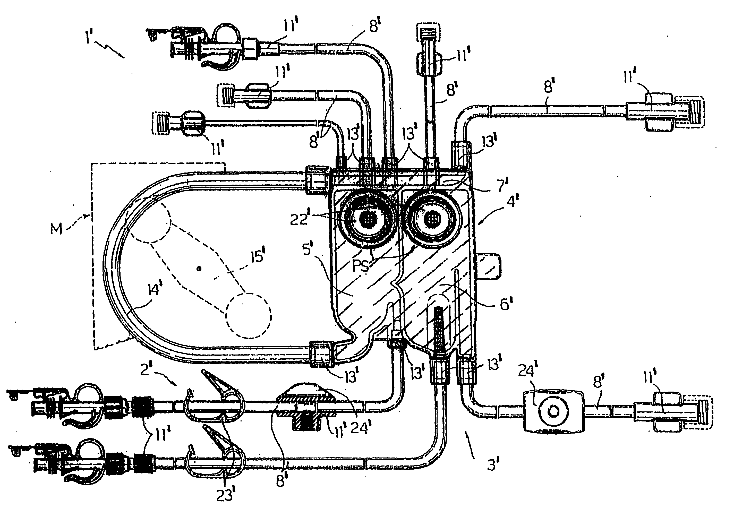
[0012] A purpose of this invention is to provide a tube for medical applications which in addition to being chlorine-free is suitable for the simple and economic manufacture of an extracorporeal circuit for a machine for the purification of blood.
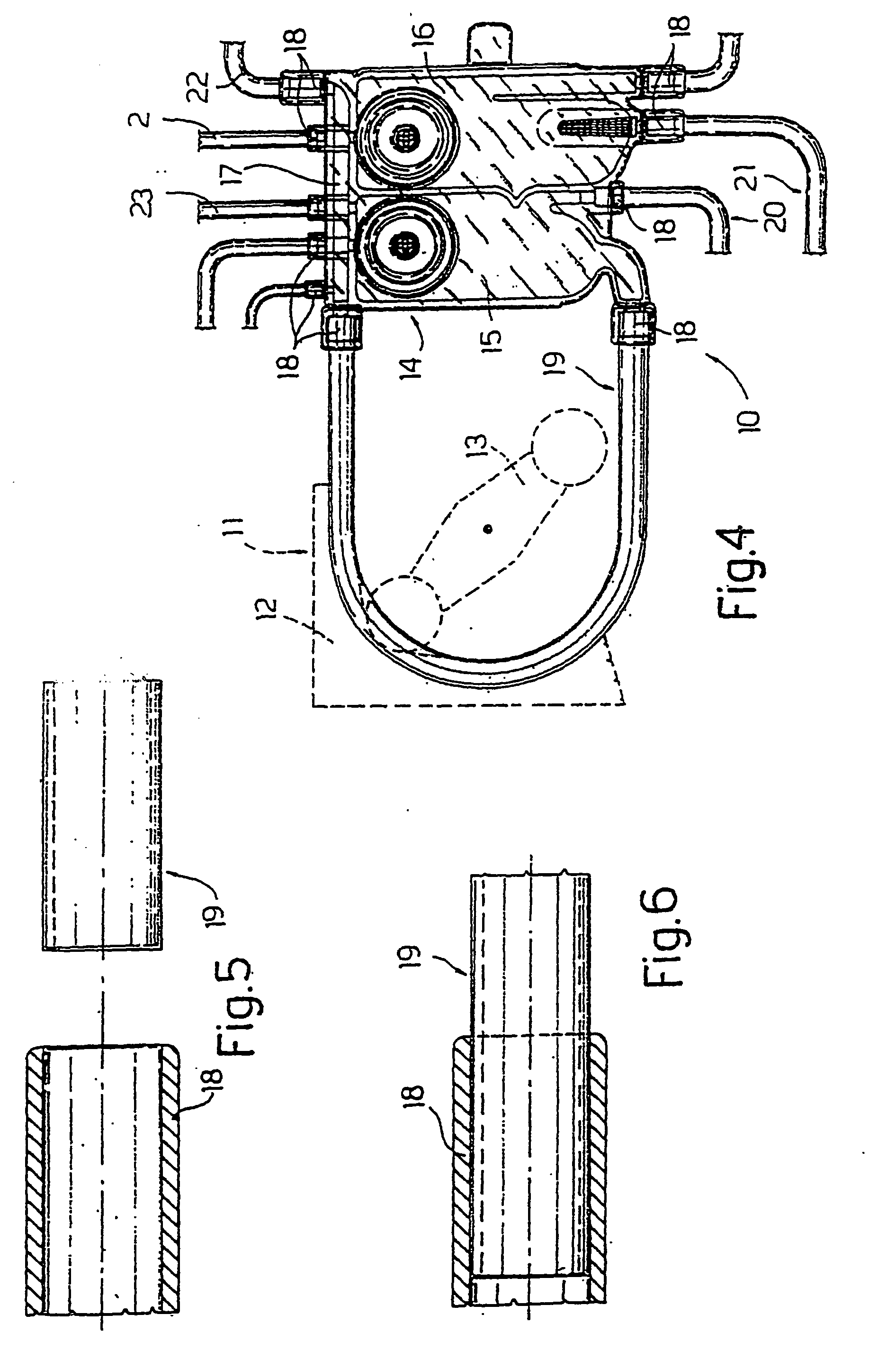
[0013] An object of the present invention is to provide an extracorporeal circuit for blood circulation comprising first components and second components welded to each other in a simple and economical way.

Problems solved by technology

Although PVC has the undoubted advantages cited above, it also has drawbacks associated with the disposal of the extracorporeal circuit.
The incineration of PVC causes the emission of substances that are harmful both to the environment and to the human body.
The substances emitted during incineration include particularly harmful ones such as hydrochloric acid (HCl), polychlorinated dibenzodioxins, and furan toxins.
Another disadvantage of the use of PVC relates to the presence of di(2-ethylhexyl)phthalate (DEHP), which is used as a plasticizer in combination with the PVC and is suspected of acting as a carcinogen.
However, these chlorine-free polymers have a number of disadvantages arising from the operations of joining the different components of the extracorporeal circuit.
In particular, these disadvantages arise from the fact that, in general, the joining operations are carried out by applying either thermal energy or radio-frequency energy to the parts included in the joints.
As a result of the heat that they inevitably produce, these joining procedures can seriously damage the tubes, to such an extent that their function is adversely affected.
Consequently, the application of a large quantity of heat, sufficient for effective welding, to small components cannot be easily controlled.

Method used


Image

  • Tube for medical applications and circuit incorporating such tube
  • Tube for medical applications and circuit incorporating such tube
  • Tube for medical applications and circuit incorporating such tube

Examples


example 1

Single-Layer Tube Manufactured from Thermoplastic Polyurethane TPU.

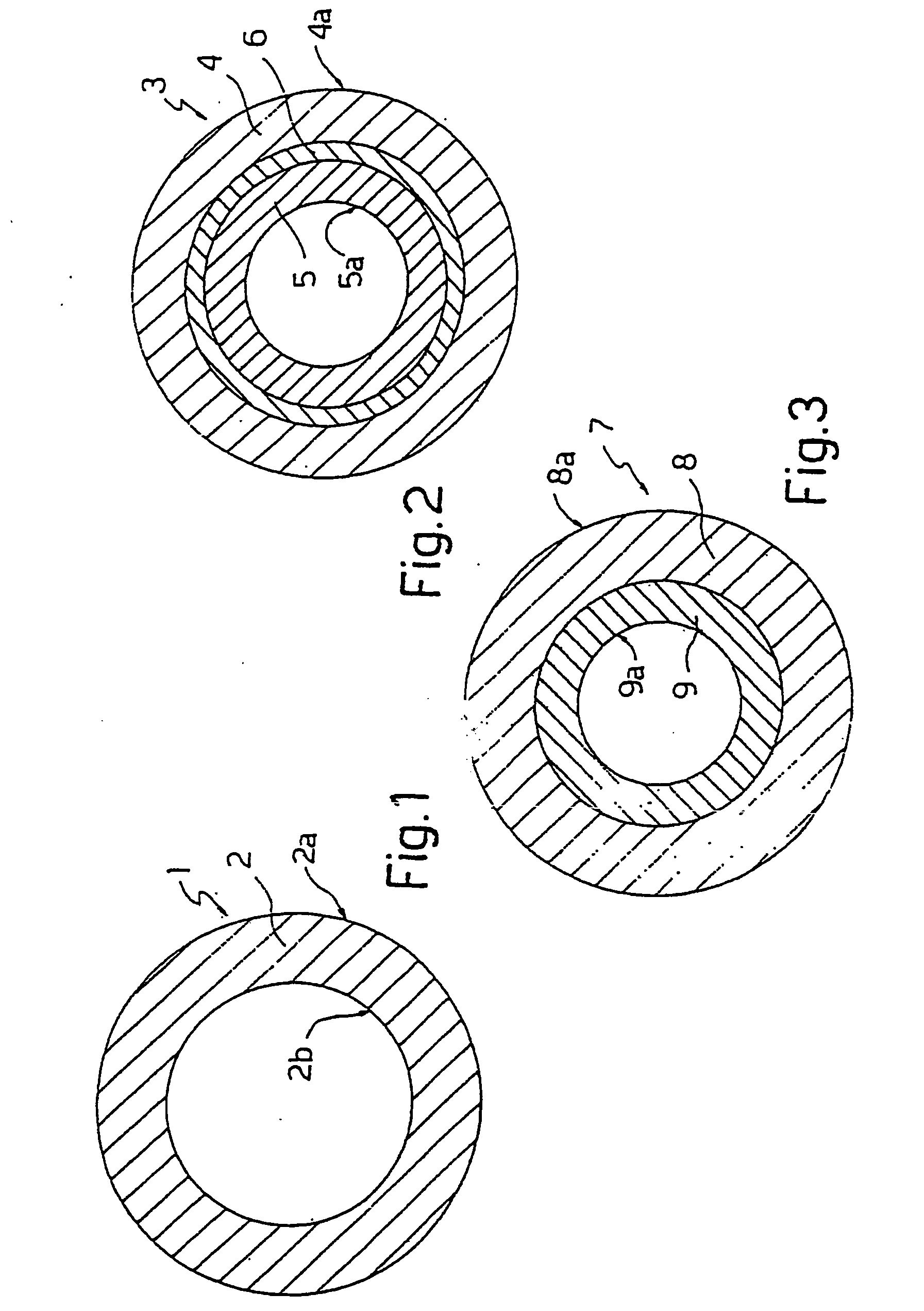
[0043] The applicant has performed tests on welding between two types of tube 1 (indicated below as tube 1A and tube 1B) manufactured from thermoplastic polyurethane and a connector 18 manufactured from PETG. Tube 1 has the following dimensions:

Tube 1A

[0044] Inside diameter 4.17 mm—Outside diameter 6.55 mm

Tube 1B

[0045] Inside diameter 6.36 mm—Outside diameter 9.54 mm

[0046] The thermoplastic polyurethane TPU used to manufacture tubes 1A was TEXIN® 5286 manufactured by Bayer, while tube 1B was manufactured from a thermoplastic polyurethane, DESMOPAN KU 2-8670 manufactured by Bayer, to which wax was added as a lubricant.

[0047] The bond was produced by applying cyclohexanone to the outer surface 2a of tube 1 along an end portion of that tube 1. The portion was inserted into connector 18, which partly dissolved on contact with the cyclohexanone placed on the aforesaid portion.

[0048] Once the action of the solve...

example 2

Multilayer Tube with an Outer Layer of Thermoplastic Polyurethane TPU.

[0050] The applicant has performed tests on welding between a tube 3 and a connector 18 manufactured from PETG.

[0051] Tube 3 had the following dimensions: Inside diameter 4.17 mm—Outside diameter 6.55 mm—Thickness of the outer layer 0.10 mm—Thickness of the inner layer 0.99 mm—Thickness of the connecting layer 0.10 mm.

[0052] The thermoplastic polyurethane TPU used to manufacture thermoplastic outer layer 4 was TEXIN® 5286 manufactured by Bayer.

[0053] Inner layer 5 was manufactured using a base material of CAVITON MED PR 4907 manufactured by Wittenburg BV—the Netherlands.

[0054] Connecting layer 6 was manufactured using a base material of CAWITON MED PR 5287 manufactured by the same Wittenburg.

[0055] The weld was made by applying cyclohexanone to the outer surface 4a of tube 3 along an end portion of that tube 3.

[0056] The portion was inserted into connector 18, which dissolved on contact with the cyclohexan...


PUM

PropertyMeasurementUnit
Lengthaaaaaaaaaa
Lengthaaaaaaaaaa
Lengthaaaaaaaaaa

Abstract

A tube for medical applications comprises a chlorine-free material and has a layer defining an outer surface of the tube. The tube is manufactured from a polymer material having a solubility parameter within the range 9.9±1.5 (cal / cm3)1 / 2.

Description

BACKGROUND OF THE INVENTION [0001] This invention relates to a tube for medical applications and to an extracorporeal circuit for blood circulation. [0002] In particular this invention relates to a tube for medical applications used to construct the extracorporeal circuit of a machine for the purification of blood. [0003] Moreover the invention relates to an extracorporeal circuit for blood circulation of a machine for blood purification, to which the present invention will make specific reference without thereby relinquishing its general applicability. [0004] A known machine for the purification of blood comprises an extracorporeal blood circuit and a blood processing unit, commonly known as a filter, which comprises a compartment through which blood passes when in use and a compartment to receive the undesired substances contained in the blood. The two compartments of the filter are separated by a semipermeable membrane. [0005] An extracorporeal blood circuit comprises, in additio...

Claims


Application Information

Patent Timeline
IPC IPC(8): A61M25/00A61M1/10A61M1/36
CPCA61M1/1037Y10T428/139A61M2205/12A61M1/367A61M60/113A61M60/279A61M60/847A61M1/36224A61M1/362261A61L29/04
Inventor GOEHL, HERMANNHANNA, MARTINMALAGOLI, MARCELLODELNEVO, ANNALISA
Owner GAMBRO LUNDIA AB
Learn More