Closed loop control for intrastromal wavefront-guided ablation with fractionated treatment program

Inactive Publication Date: 2005-07-07
TECHNOLAS PERFECT VISION
View PDF16 Cites 10 Cited by
  • Summary
  • Abstract
  • Description
  • Claims
  • Application Information

AI Technical Summary

Benefits of technology

[0010] In a complicated procedure such as a corneal reshaping, it would be helpful to predict the long term surgical effect of an ablation (i.e. the eventual corneal shape after bubble collapse and relaxation of photoablation induced stresses). Preferably, this prediction could be made in real-time from a wavefront measurement that is obtained during a procedure (i.e. after an ablation but before the resulting bubble has collapsed). This information could then be used to modify a treatment plan during the procedure, to increase the overall accuracy of the procedure. As recognized by the present invention, however, the relaxation of induced stresses which occurs during the second period described above, and its effect on corneal shape, is somewhat unpredictable. At least this is so using current models. On the other hand, the inventors have determined that it is possible to estimate the corneal shape after bubble collapse (i.e. at the end of the second period described above). Moreover, this can be done with real-time wavefront data measured between successive bubbles during a procedure.
[0011] In light of the above, it is an object of the pres

Problems solved by technology

This is not the case, however, when internal tissue is photoablated.
For specific surgical procedures that involve the intrastromal photoablation of corneal tissue, it is known that such photoablation results in the formation of tiny bubbles in the stroma.
Further, it is kno

Method used


Image

  • Closed loop control for intrastromal wavefront-guided ablation with fractionated treatment program
  • Closed loop control for intrastromal wavefront-guided ablation with fractionated treatment program
  • Closed loop control for intrastromal wavefront-guided ablation with fractionated treatment program

Examples


Embodiment Construction

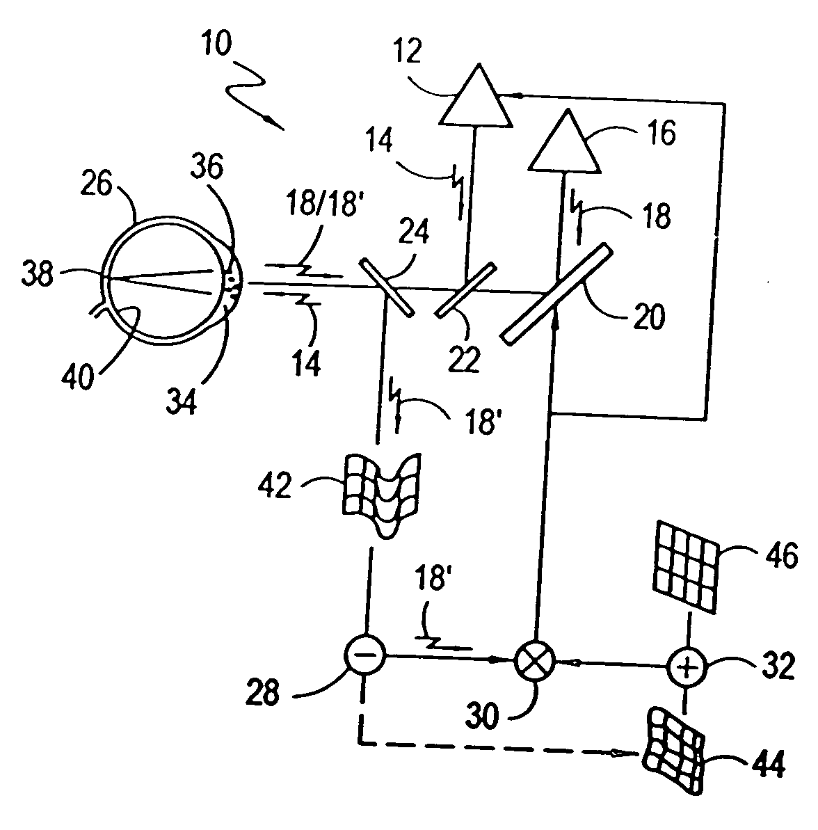
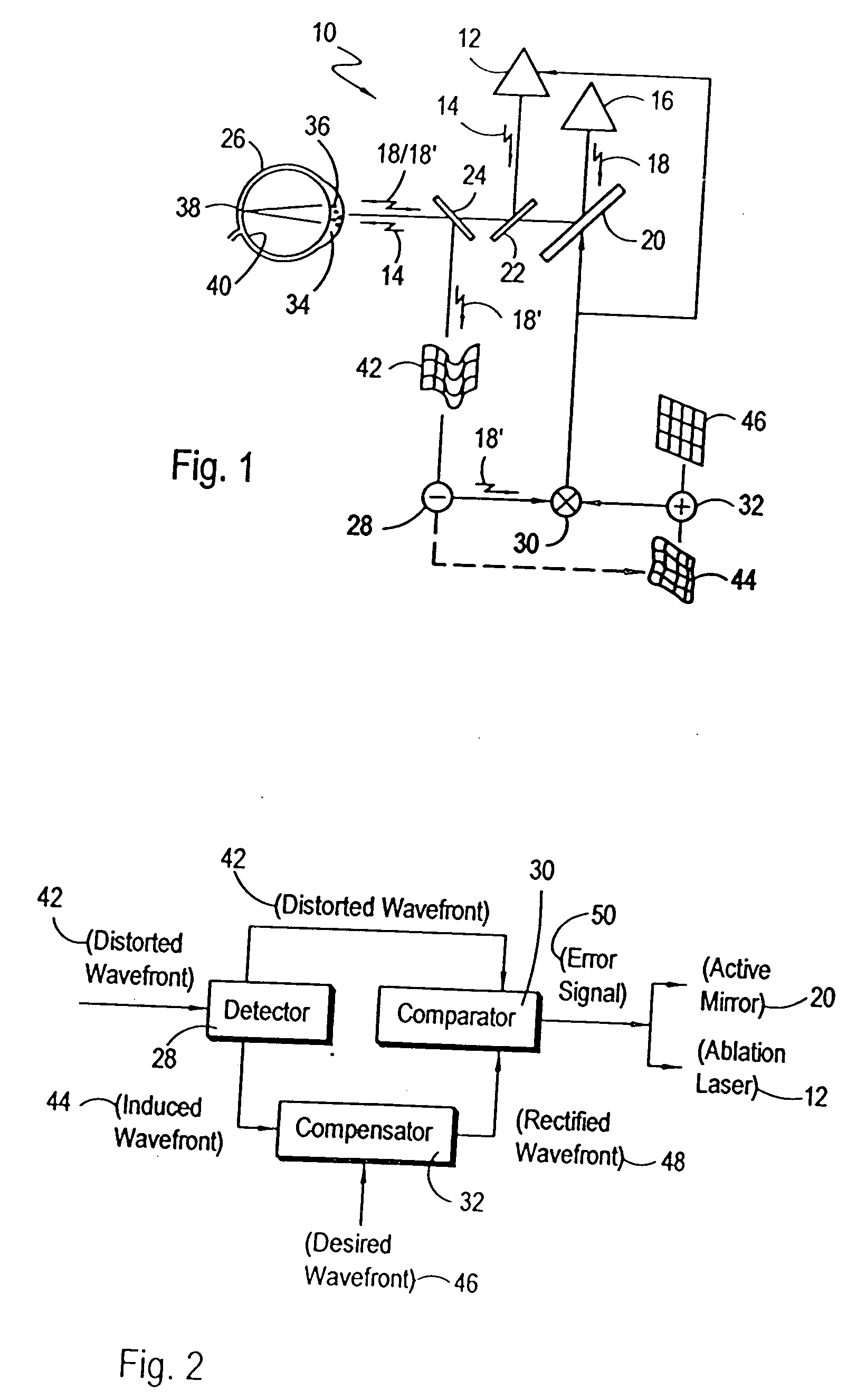
[0032] Referring initially to FIG. 1, a closed-loop system for intrastromal photoablation of corneal tissue in accordance with the present invention is shown and is generally designated 10. In detail, the components of system 10 include a source 12 for generating an ablation laser beam 14, and a source 16 for generating a diagnostic laser beam 18. Further, the system 10 includes an active, multi-facet mirror 20, a beam splitter 22 and a beam splitter 24. More particularly, the active mirror 20 is preferably of a type disclosed in U.S. Pat. No. 6,220,707 which issued to Bille for an invention entitled “Method for Programming an Active Mirror to Mimic a Wavefront” and which is assigned to the same assignee as the present invention. As shown, the active mirror 20 and the beam splitters 22 and 24 direct the diagnostic laser beam 18 from diagnostic laser source 16 toward an eye 26. Likewise, the beam splitters 22 and 24 are used to direct the ablation laser beam 14 from the ablation lase...


PUM


Abstract

A closed-loop control system for altering the optical characteristics of a patient's cornea includes an algorithm for predicting the shape of the cornea after one or more gas bubbles resulting from intrastromal photoablation have collapsed. Patient data can be used as an input for the algorithm, which is then run to prepare an initial treatment plan for a corneal alteration. The initial plan typically includes a plurality of intrastromal photoablation locations and corresponding ablation energies. After photoablation of plan location(s) and before the resulting bubbles collapse, a real-time wavefront shape for light passing through the cornea is measured. The wavefront is then used in the algorithm to predict a post bubble collapse cornea shape and to generate an updated treatment plan. The procedure then continues by ablating location(s) identified in the updated treatment plan. Wavefront measurement and plan updating can be repeated as many times as desired.

Description

[0001] This application is a continuation-in-part of application Ser. No. 10 / 293,226 filed Nov. 13, 2002, which is currently pending. The contents of application Ser. No. 10 / 293,226 are incorporated herein by reference.FIELD OF THE INVENTION [0002] The present invention pertains generally to laser systems that photoablate corneal tissue to improve the visual acuity of an eye. More particularly, the present invention pertains to laser systems and methods that perform intrastromal photoablation of tissue during corrective optical surgery. The present invention is particularly, but not exclusively, useful as a real-time, closed-loop control system which measures the effect of photoablation during a procedure and uses the measured data to update a photoablation treatment plan during the procedure. BACKGROUND OF THE INVENTION [0003] It is well known that the optical characteristics of an eye can be altered through laser surgery. For example, U.S. Pat. No. 6,050,687 which issued to Bille ...

Claims


Application Information

Patent Timeline
IPC IPC(8): A61F9/007A61B17/00A61F9/01
CPCA61B3/1015A61B3/107A61B2017/00017A61B2017/00022A61F2009/0088A61F9/00829A61F2009/00848A61F2009/00872A61F9/008
Inventor BILLE, JOSEF
Owner TECHNOLAS PERFECT VISION
Why Eureka
Try Eureka