
Ablation burr

Inactive Publication Date: 2005-07-07
BOSTON SCI SCIMED INC
View PDF14 Cites 74 Cited by
  • Summary
  • Abstract
  • Description
  • Claims
  • Application Information

AI Technical Summary

Benefits of technology

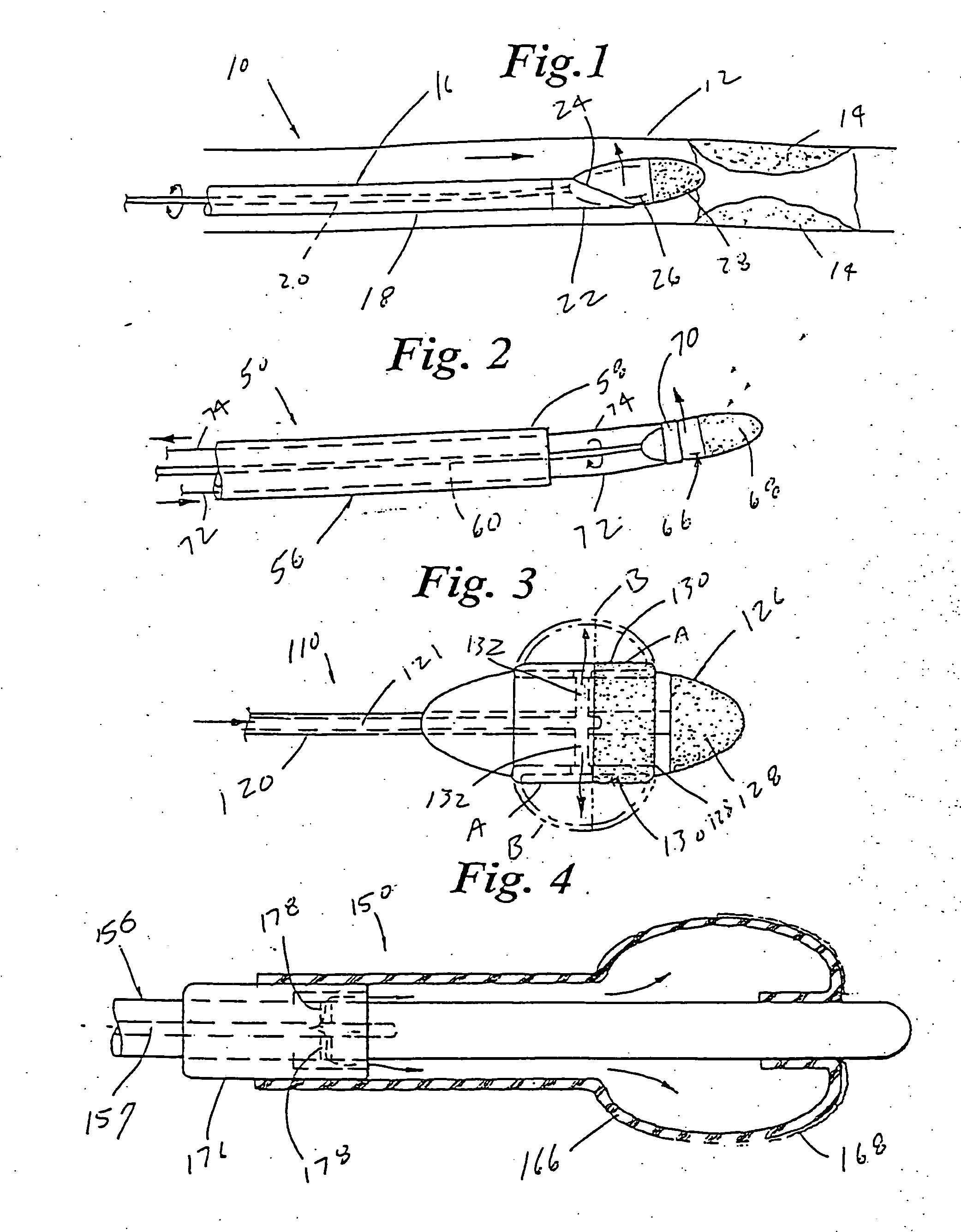
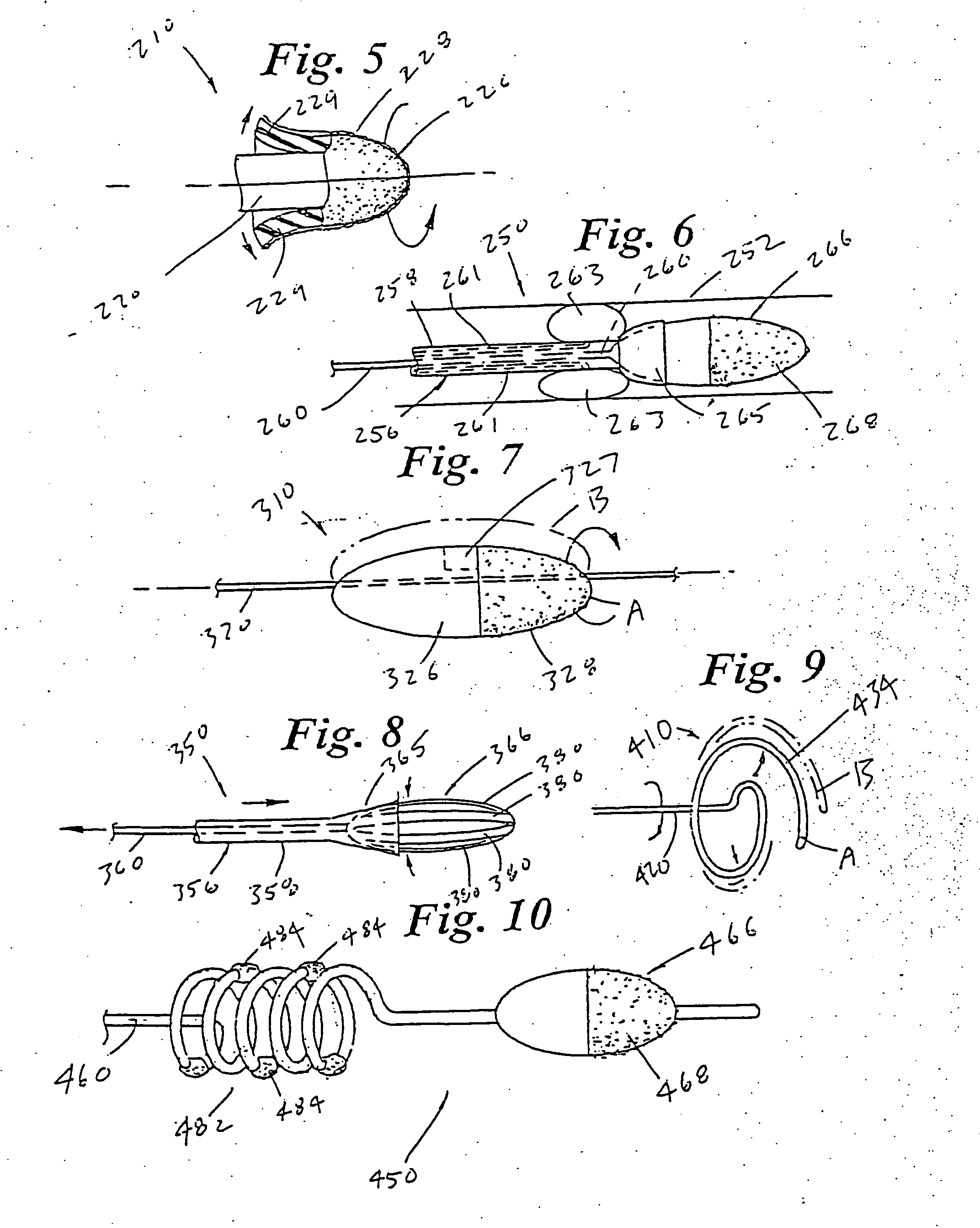
[0015] In another embodiment of the atherectomy device in accordance with the present invention, an elongate rotatable drive shaft is provided having a proximal end and a distal end. A lumen is defined through the elongate drive shaft. A balloon including an outer surface and defining a balloon enclosure in fluid communication with the inflation lumen is disposed at the distal end of the drive shaft. An abrasive is disposed on the outer surface of the balloon. The balloon can be dilated by pressure or centrifugal force to increase the transverse dimension of the abrasive surface.

Problems solved by technology

This can be particularly serious if, for example, such an occlusion occurs in a portion of the vasculature that supplies vital organs with blood or other necessary fluids.
It is to be noted, however, that this procedure does not remove the occluding matter from the patient's vasculature, but displaces it.
While balloon angioplasty is quite successful in substantially revascularizing many vascular lumens by reforming the occluding material, other occlusions may be difficult to treat with angioplasty.
Even if angioplasty is successful, thereby revascularizing the vessel and substantially restoring normal blood flow therethrough, there is a chance that the occlusion may recur.
Since vascular occlusions may have different compositions and morphology or shape, a given removal or cutting element may not be suitable for removal of a certain occlusion.
This type of procedure can be quite expensive because multiple pieces of equipment may need to be used (such intravascular devices are not reusable because they are inserted directly into the blood stream), and may be tedious to perform because multiple pieces of equipment must be navigated through an often-tortuous vascular path to the treatment site.

Method used


Image

  • Ablation burr
  • Ablation burr
  • Ablation burr

Examples


Embodiment Construction

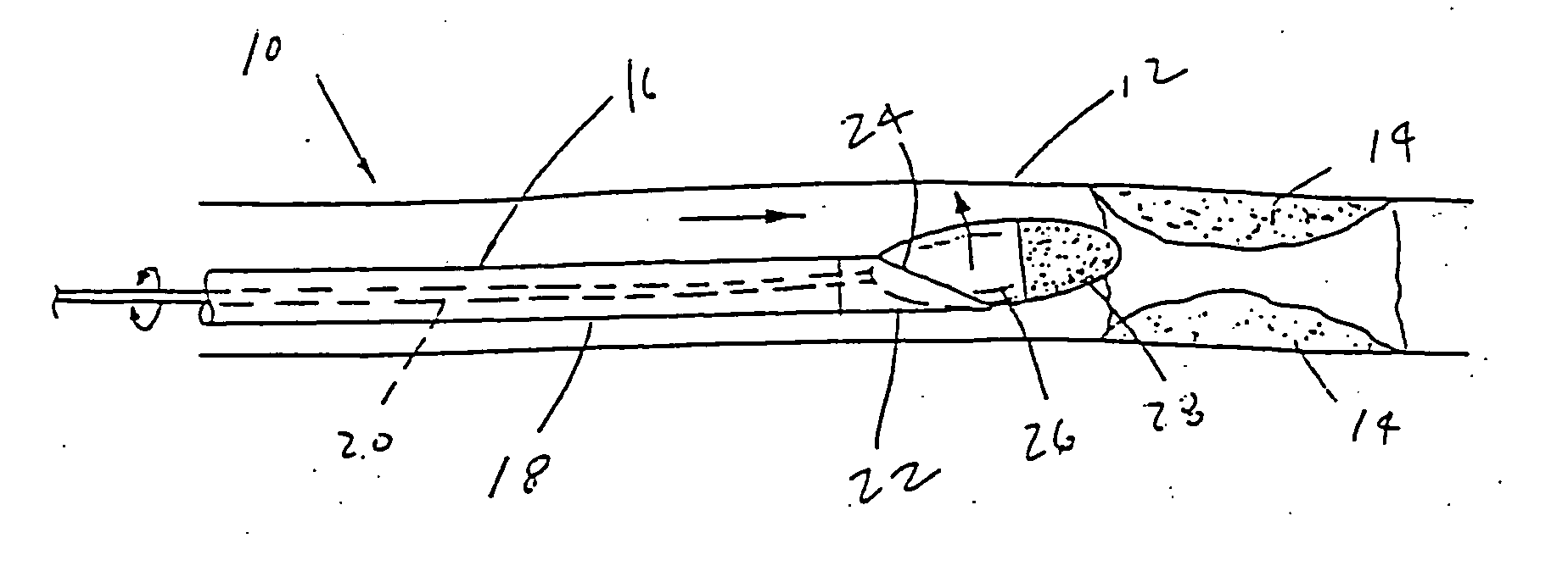
[0039] Referring now to the drawings, wherein like reference numerals refer to like reference elements throughout the several views, FIGS. 1 is a side view of catheter 10 in accordance with the present invention. As shown in FIG. 1, catheter 10 is disposed within vessel 12 proximate a plaque deposit 14. Catheter 10 includes an elongate shaft 16. Shaft 16 includes an outer shaft 18 having a proximal end a distal end and defining a drive shaft lumen therethrough. Catheter 16 also includes a drive shaft 20 having a proximal end a distal end and extending through outer shaft 18. Disposed at the distal end of outer shaft 18 is a burr deflector 22 having a burr engaging surface 24. Disposed at the distal end of drive shaft 20 is a burr 26 rotatable by drive shaft 20, and including an abrasive surface 28.

[0040] As will be appreciated by those skilled in the art, suitable manifold and motor can be provided at the proximal end of catheter 10 to rotate burr 26 and facilitate the uses of cath...


PUM


Abstract

A catheter including an elongate drive shaft having a proximal end and a distal end, an ablation burr disposed at the distal end expandable between a first position and a second position, wherein in the second position has a greater transverse dimension than in the first position. The catheter of the present invention can include a mechanism for positioning the burr eccentrically within a vessel lumen. In this context, expansion means that the burr can ablate a lumen having a larger diameter than the diameter of the lumen of the guide catheter to which the device is advanced.

Description

BACKGROUND OF THE INVENTION [0001] The present invention generally relates to constructions for intravascular treatment devices useful for removing vascular occlusion material from a vascular occlusion or from a vascular lumen. The invention more specifically relates to “expandable” intravascular occlusion material removal devices, as well as to methods of using those devices to treat vascular diseases. In this context, “expandable” means that the burr can ablate a lumen having a larger diameter than the diameter of the lumen of the guide catheter to which the burr is advanced. [0002] Vascular diseases, such as atherosclerosis and the like, have become quite prevalent in the modern day. These diseases may present themselves in a number of forms. Each form of vascular disease may require a different method of treatment to reduce or cure the harmful effects of the disease. Vascular diseases, for example, may take the form of deposits or growths in a patient's vasculature which may res...

Claims


Application Information

Patent Timeline
IPC IPC(8): A61B17/00A61B17/22A61B17/32
CPCA61B17/320725A61B17/320758A61B2017/003A61B2017/320766A61B2017/00867A61B2017/320004A61B2017/320733A61B2017/00557
Inventor KANZ, BILLDRUMMOND, DENISEBARRY, ROBERTHIRST, PAUL A.WYZGALA, MARKSWINFORD, GARYWULFMAN, EDWARDCLEMENT, TOMKADAVY, TOM
Owner BOSTON SCI SCIMED INC
Learn More