Minimal injury resorbable stent

a resorbable, minimally injured technology, applied in the field of resorbable stents, can solve the problems of prolonging the angioplasty treatment, increasing the cost, and unfavorable local thrombosis, and achieves high molecular alignment or orientation, enhanced properties

Inactive Publication Date: 2005-07-07
MEDTRONIC VASCULAR INC
View PDF12 Cites 39 Cited by
  • Summary
  • Abstract
  • Description
  • Claims
  • Application Information

AI Technical Summary

Benefits of technology

[0012] It has been found that minimal injury resorbable stents having enhanced properties can be produced by introducing high levels of molecular alignment or orientation in the resorbable materials used in stent production. The present invention, therefore, relates to a method of controlling the morphology of the oriented resorbable materials and a method of manufacturing a low profile stent comprising the oriented resorbable materials.

Problems solved by technology

In addition, some implanted stents have been found to cause undesired local thrombosis.
To address this, some patients receive anticoagulant and antiplatelet drugs to prevent local thrombosis or restenosis, however this prolongs the angioplasty treatment and increases its cost.
The use of resorbable polymers, however, has drawbacks that have limited the effectiveness of polymeric stents in solving the post-surgical problems associated with balloon angioplasty.
The limitations in mechanical strength of the resorbable stents can result in stent recoil after the stent has been inserted.
This makes stent delivery more difficult and can cause a reduction in the area of flow through the lumen.
A larger strut area also increases the level of injury to the vessel wall and this may lead to higher rates of restenosis i.e. re-occlusion of the vessel.

Method used


Image

  • Minimal injury resorbable stent
  • Minimal injury resorbable stent
  • Minimal injury resorbable stent

Examples


Embodiment Construction

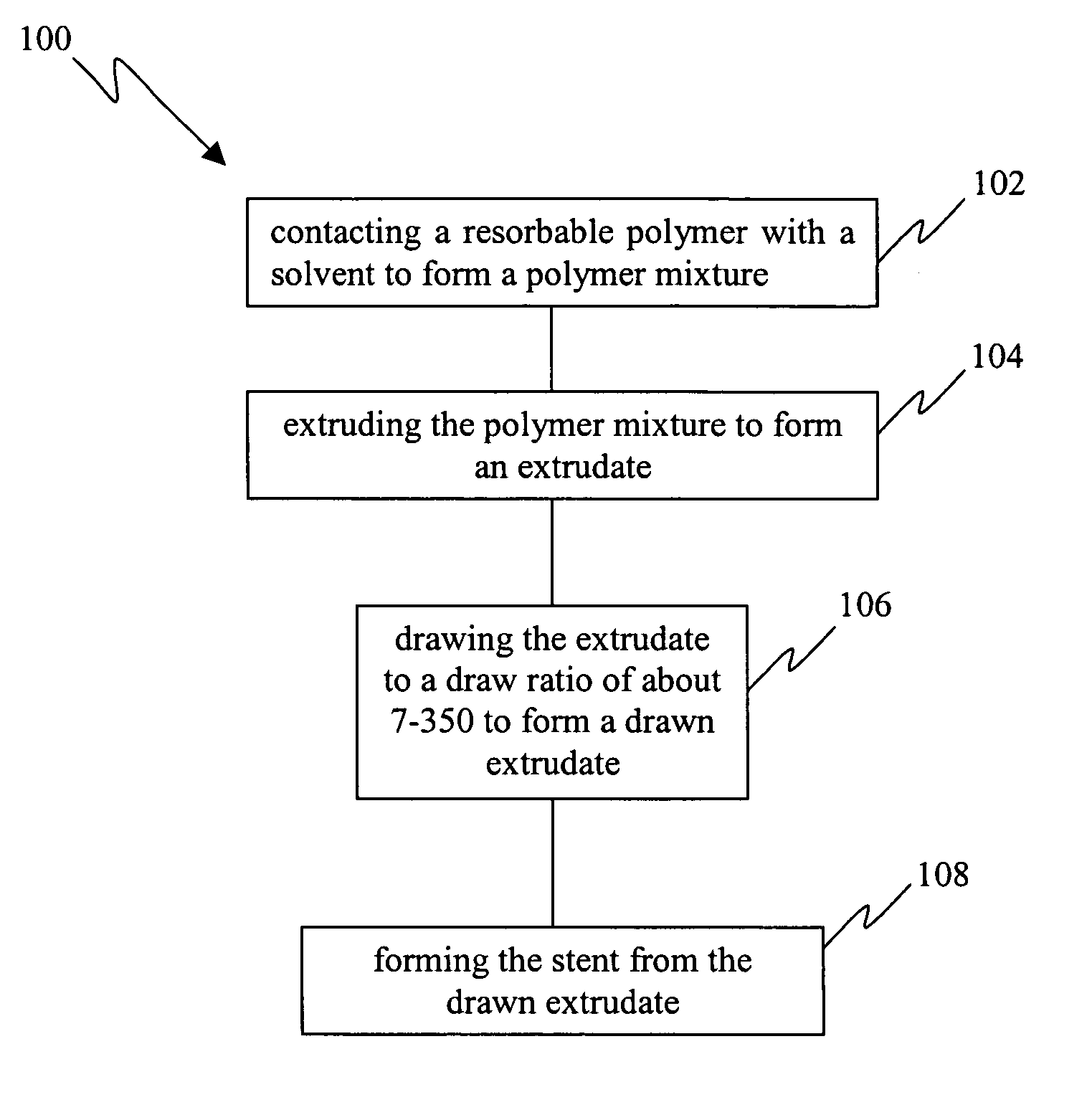
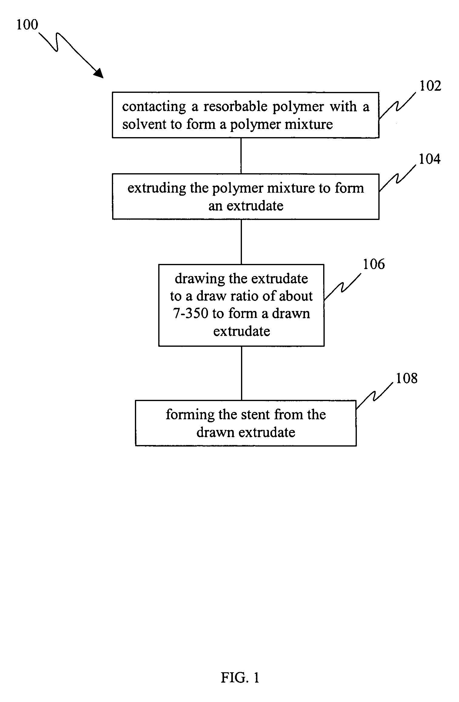
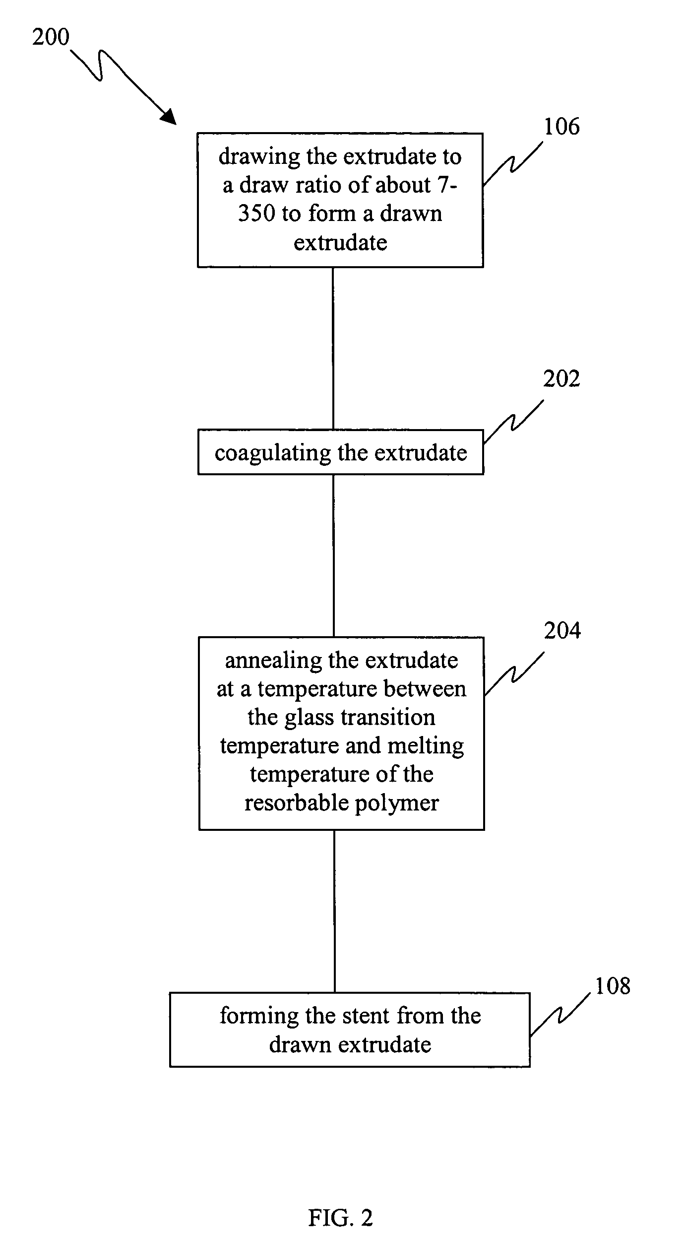
[0020] Reference will now be made in detail to the embodiments of the present invention, examples of which are illustrated in the accompanying drawings.

[0021] Resorbable polymers extruded via conventional melt extrusion exhibit relatively high entanglement densities and this serves to limit the ultimate draw ratios (typically less than 10) and therefore the tensile strengths that may be achieved for these polymers. The traditional method to achieve chain orientation is based on drawing a melt extruded or molded polymer, often semi-crystalline, in the solid state at temperatures above its glass transition temperature. In this state, chain mobility is likely to be limited by entanglements as well as chain interactions and crystallinity. Therefore, it is also likely that entanglements, chain folds, and fragments of crystals survive the drawing process (which allows only limited drawing) and persist in the drawn polymer as defects which serve to limit the strength. The limitations impo...


PUM

PropertyMeasurementUnit
tensile strengthaaaaaaaaaa

Abstract

A minimal injury resorbable stent comprising an oriented resorbable material drawn to a ratio about 7-350 is disclosed. The drawn materials of the present invention have tensile strength of about 50-500 MPa and Young's modulus of about 2-300 GPa. The bioresorbable stents can have cylindrical shape and optionally further comprise one or more of a solvent, plasticizer, biologically active agent and modifier. Also disclosed is a method for manufacturing a minimal injury resorbable stent. The process comprises contacting a resorbable polymer with a solvent to form a polymer mixture, extruding said polymer mixture to form an extrudate, drawing said extrudate to a draw ratio in the range of about 7-350 to form a drawn extrudate and forming said stent from said drawn extrudate. The process optionally further comprises coagulating the extrudate and annealing the extrudate and / or stent.

Description

BACKGROUND OF THE INVENTION [0001] 1. Field of the Invention [0002] The present invention relates to the field of resorbable stents. [0003] Specifically, the present invention relates to minimal injury resorbable stents and a process for their manufacture. [0004] 2. Related Art [0005] Stents have gained acceptance in the medical community as a device capable of supporting body lumens, such as blood vessels, that have become weakened or are susceptible to closure. Typically, a stent is inserted into a vessel of a patient after an angioplasty procedure has been performed to partially open up the blocked / stenosed vessel thus allowing access for stent delivery and deployment. After the catheter used to perform angioplasty has been removed from the patient, a tubular stent, maintained in a small diameter delivery configuration at the distal end of a delivery catheter, is navigated through the vessels to the site of the stenosed area. Once positioned at the site of the stenosis, the stent...

Claims


Application Information

Patent Timeline
Patent Type & Authority Applications(United States)
IPC IPC(8): A61F2/02A61F2/06A61L31/14D01F4/00D01F6/62
CPCA61F2/06A61F2210/0004D01F6/625D01F4/00D01F6/62A61L31/148
Inventor VARMA, ASHISH
Owner MEDTRONIC VASCULAR INC
Why Eureka
Try Eureka