Eigen decomposition based OPC model

a decomposition and opc model technology, applied in the field of eigen decomposition based opc model, can solve the problems of significant deterioration in image quality and photolithography process robutstness, the cd resolution limit of the optical exposure tool, and the size of the integrated circuit is reduced, so as to achieve the effect of minimal human intervention

Inactive Publication Date: 2005-07-07
ASML NETHERLANDS BV
View PDF21 Cites 76 Cited by
  • Summary
  • Abstract
  • Description
  • Claims
  • Application Information

AI Technical Summary

Benefits of technology

[0037] In accordance with the principles of the present invention, a systematic methodology can be utilized that converts the features in a CD SEM image into contours, with minimum human intervention.

Problems solved by technology

These rules are set by processing and design limitations.
As the size of an integrated circuit is reduced and its density increases, however, the CD of its corresponding mask pattern approaches the resolution limit of the optical exposure tool.
As the technology advances in the semiconductor industry, the dimensions on a circuit have scaled down dramatically, which leads to significant deterioration in image quality and photolithography process robutstness.
To further shorten the exposure wavelength beyond 193 nm or to further increase the numerical aperture beyond 0.9 presents enormous obstacles both economically and technically.
Although scattering bar placement rules can be generated from optical imaging theory without taking the resist effect into account, the correct amount of biasing of the mask data at a given location can never be predicted accurately without considering the effect of the resist.
This character leads to its simplicity in implementation, but it also intrinsically sets the limitation of its accuracy.
This trial and error process, which can entail repeated mask revisions followed by repeated simulations, can become both a time consuming and costly process.
These are labor intensive and time consuming work.
Worse, how the measurement CDs were taken can often become operator dependent due to the experience level, which can obviously impact the parameter calibration negatively, thereby limiting the overall effectiveness of the technique.
However, these models are facing ever-increasing challenges in meeting the more stringent dimension control requirements in low k1 photolithography.
Those models are also very likely to fail in working with the new advanced photolithography technologies, such as Chromeless Phase Lithography (CPL) in which the topography on the mask is rather significant, and Double Dipole Lithography (DDL) in which two masks and two exposures are needed.
In addition to those concerns, advanced illuminations such as customer designed illuminators using diffractive optical elements (DOE), deviations of real illuminator profiles from theoretical top-hat illuminator profiles are all presenting enormous challenges to the current available models.
However, currently illumination optimization and mask optimization are not generally linked.
Rosenbluth also recognizes that the calculations may be limited relying on the symmetry of a mask.
However, the linearization of the mask transmission used by Rosenbluth requires using several approximations in the calculations, instead of the actual imaging equations themselves, which produce errors in implementing a mask to form a desired image.
The linearization of the mask transmission also requires the use of a significant number of variables, which requires significant computation time to perform the calculations.

Method used


Image

  • Eigen decomposition based OPC model
  • Eigen decomposition based OPC model
  • Eigen decomposition based OPC model

Examples


Embodiment Construction

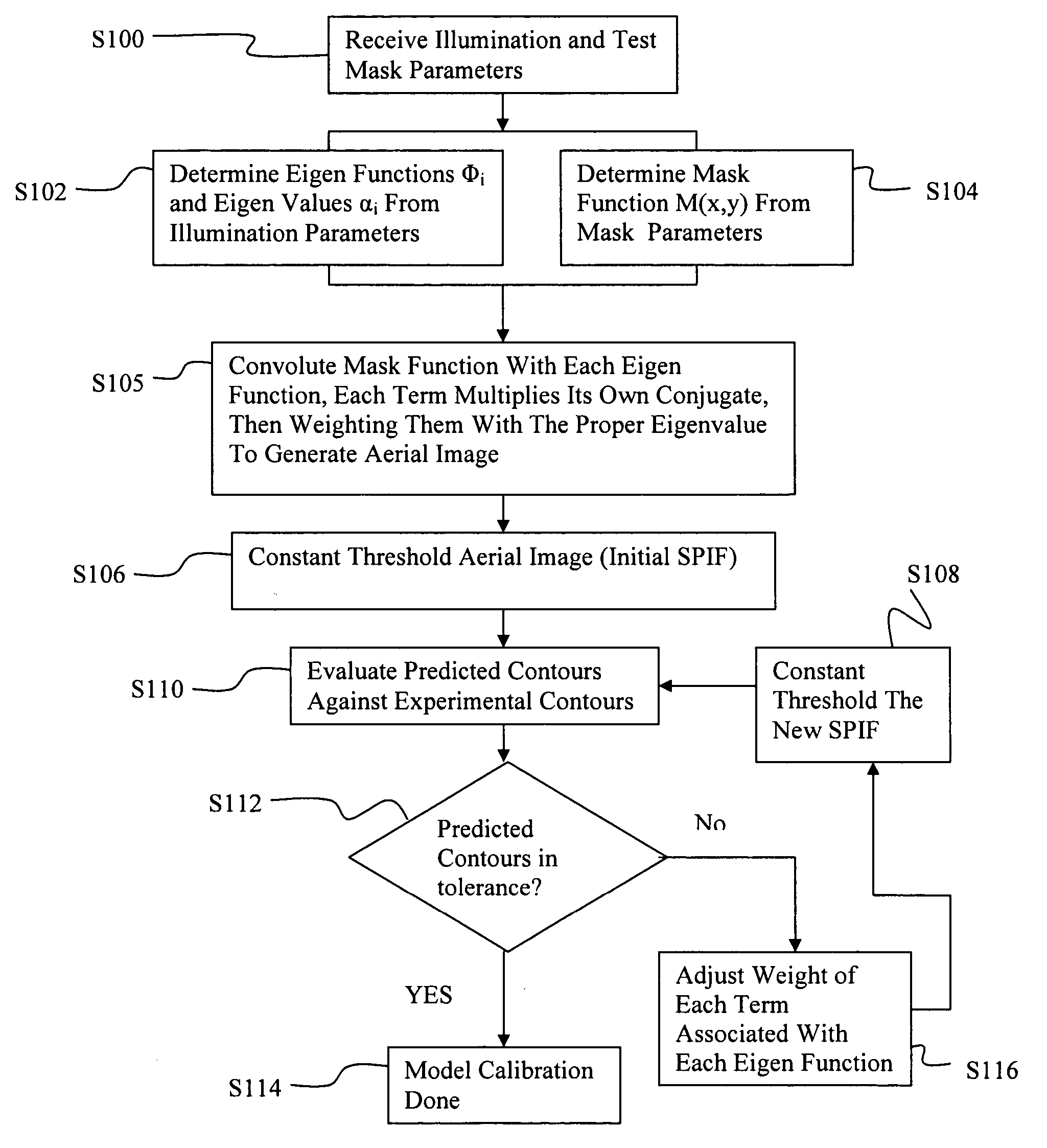
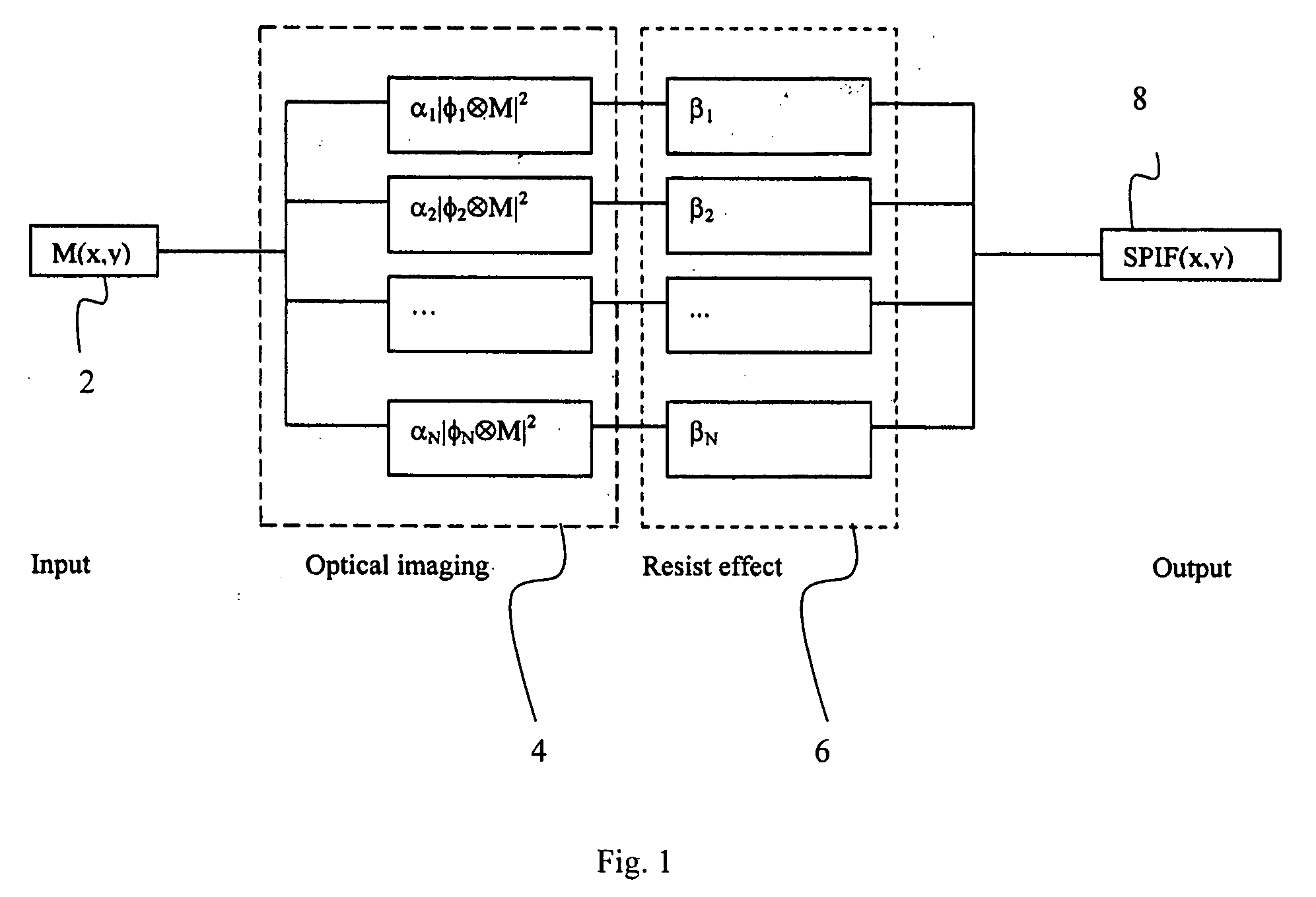
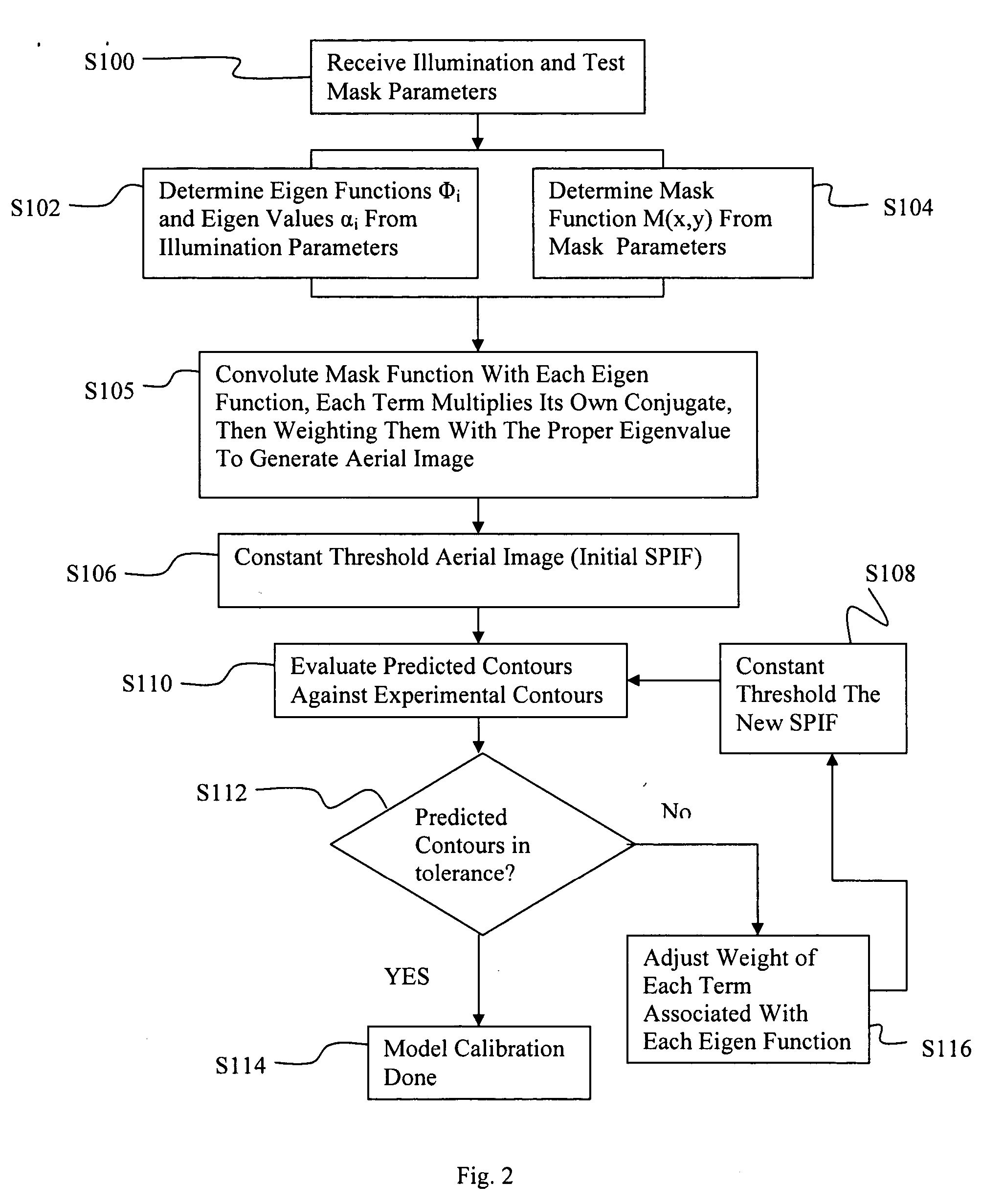
[0051] Disclosed is a method and system for model OPC that is based on eigen function decomposition (termed as Eigen Decomposition Model, or EDM). In the present invention, a partially coherent imaging system is preferably decomposed into a series of coherent imaging systems. The series of coherent imaging systems provide an effective and accurate way to describe the aerial image intensity distribution around a point of interest (x, y), which may be used to design an improved mask to improve the resolution of the desired image features in the photolithography process. For a precision model OPC on the mask pattern, we must ensure the illumination impact is well accounted for. For a tractable model OPC application, the present invention utilizes an eigen function decomposition approach to optimally approximate a partial coherence imaging system. The optimal approximation is used to generate a model which may be used to generate a SPIF function for each mask, which may be used by a com...


PUM

PropertyMeasurementUnit
exposure wavelengthaaaaaaaaaa
wavelengthaaaaaaaaaa

Abstract

Model OPC is developed based on eigen decomposition of an aerial image expected to be produced by a mask pattern on a surface of a resist. With the eigen decomposition method the aerial image intensity distribution around a point (x, y) is accurately described in the model. A scalar approach may be used in the eigen decomposition model which treats the light wave through the mask as a scalar quantity. A eigen decomposition alternatively may use a vector approach which utilizes a vector to describe the light wave and the pupil function. A predicted SPIF may be generated from the aerial image which may be used to verify the mask modeling process by comparing the predicted SPIF to an experimentally determined SPIF. The model OPC, once calibrated, may be used to evaluate performance of a mask and refine features of the mask.

Description

[0001] This application claims the benefit of provisional application 60 / 517,083, filed on Nov. 5, 2003 titled MODEL OPC IMPLEMENTATION WITH GENERALIZED ILLUMINATION and also claims the benefit of provisional application 60 / 605,716 filed on Aug. 31, 2004, titled VECTOR EIGEN DECOMPOSITION BASED OPC MODEL, each of which are herein incorporated by reference in their entirety.FIELD OF THE INVENTION [0002] The field of the invention relates generally to a method, apparatus and program product for preventing optical proximity correction to target mask patterns. The present invention more particularly relates to a method, apparatus and program product for generating a model of the imaging process which can be utilized to simulate the aerial image of the imaging process for any given input mask pattern. BACKGROUND [0003] Lithographic apparatus can be used, for example, in the manufacture of integrated circuits (ICs). In such a case, the photolithographic mask may contain a circuit pattern ...

Claims


Application Information

Patent Timeline
Patent Type & Authority Applications(United States)
IPC IPC(8): G03F1/00G03F1/36G03F7/20G06F17/50G06K9/00H01L21/027
CPCG03F1/144G03F7/705G03F1/36G03F7/70441
Inventor SHI, XUELONGSOCHA, ROBERT J.LAIDIG, THOMASBROEKE, DOUGLAS VAN DEN
Owner ASML NETHERLANDS BV
Why Eureka
Try Eureka