

Xerographic printing system with VCSEL-micro-optic laser printbar
a laser print bar and laser printing technology, applied in printing and other directions, can solve the problems of impracticality, inability to accurately measure the depth of focus, and inability to efficiently collect the emitted beam, so as to achieve the effect of reducing the source size, reducing the depth of focus, and working distan
- Summary
- Abstract
- Description
- Claims
- Application Information
AI Technical Summary
Benefits of technology
Problems solved by technology
Method used
Image

Examples
example 1
Optical System Analysis of 1-D Printbar Using Micro-Optics
[0034] A 1st order optical system analysis example of a linear VCSEL array with micro-optics follows. The example is calculated using standard Gaussian beam propagation equations applied to a VCSEL 1-D printbar with a desired print resolution of 600 DPI, where the VCSEL laser emitters of the array have a wavelength of 780 nm, and the VCSEL has a spot size at FWHM of approximately 4.415 μm.
[0035] FWHMVCSEL=˜4.415 μm
[0036] Cross process direction raster frequency=Rxp=600 SPI
[0037] Spot separation=1 / Rxp=Raster Spacing on P / R=42.3 μm
[0038] Magnification of micro-optic=−4
[0039] Focal length of micro-optic=226.6 μm
[0040] Diameter of micro-optic lens=46 μm to 62 μm
[0041] VCSEL to micro-optic distance=226.6 μm
[0042] FWHM at micro-optic image plane=17.7 μm
[0043] Micro-optic to micro-optic image plane=226.6 μm
[0044] Micro-optic image plane to P / R plane=1.974 mm
[0045] FWHM at P / R=42.3 μm
[0046]±10% spot size depth of focus˜±...
example 2
Comparative Example without Micro-Optics
[0048] A 1st order optical system analysis example of a linear VCSEL array without micro-optics having all other system design parameters as described in Example 1 follows:
[0049] VCSEL printbar P / R distance=0.54 mm
[0050]±10% spot size depth of focus˜±55 μm
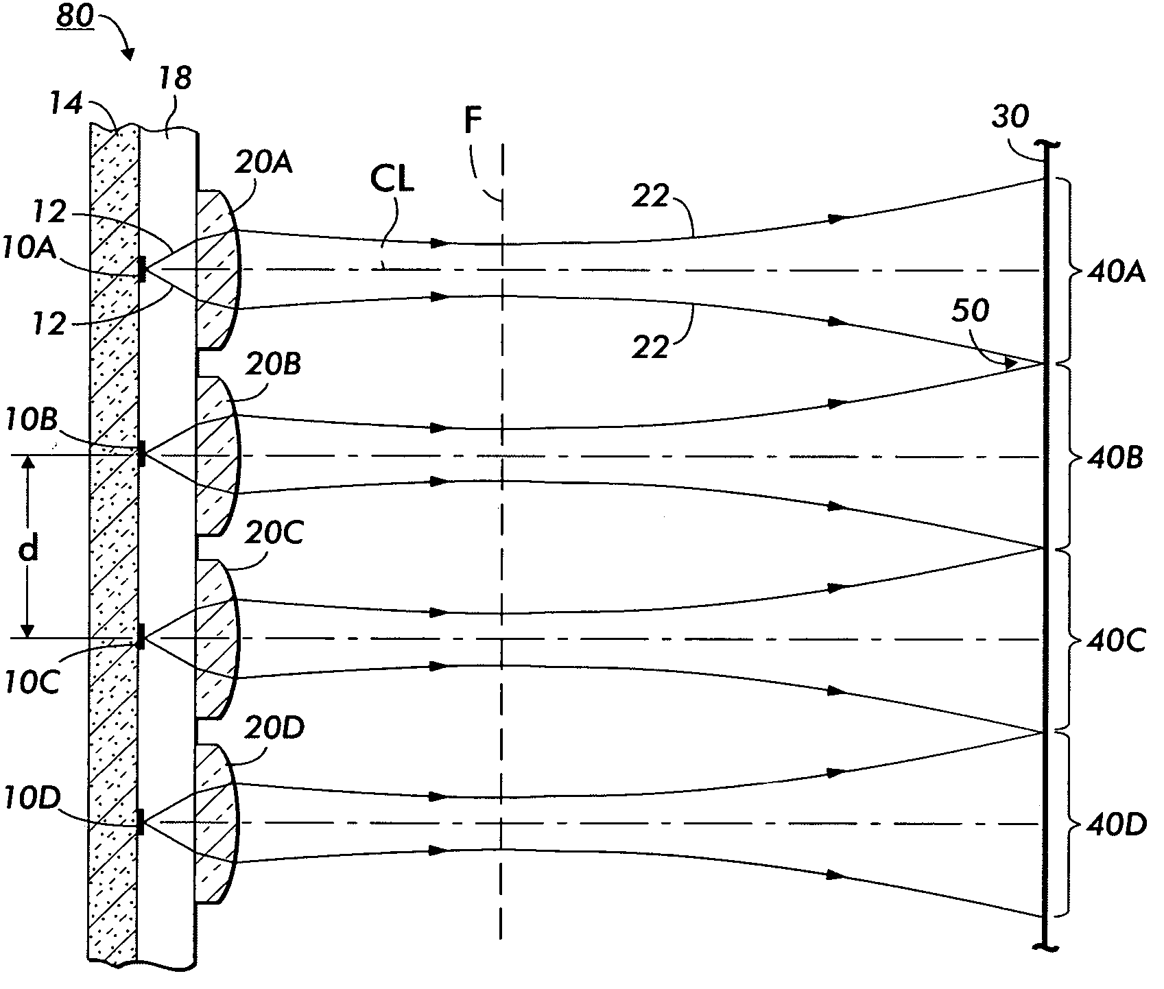
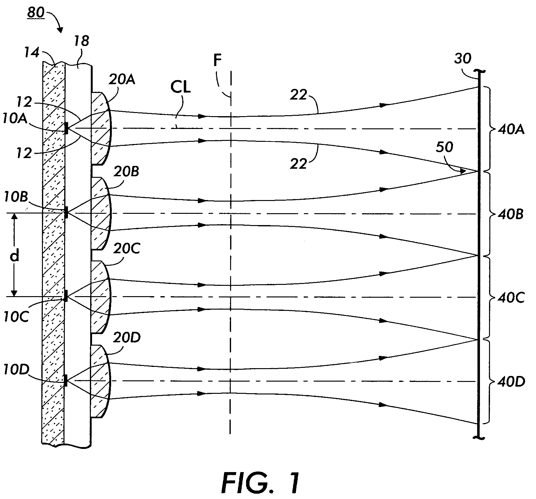
[0051] As shown in Examples above, the critical parameters including depth of focus, spot separation relative to the VCSEL spot size, and micro-optic lens diameter relative to spot separation become impracticable and, in some cases, physically impossible for raster frequencies>600 SPI (“scans per inch”).
[0052] For raster frequencies>600 SPI, one practical printbar solution is found in using 2-D VCSEL arrays with micro-optics, as described herein. If the photoreceptor 30 could be placed at the micro-optic image plane F the depth of focus would be maximized (˜2.9 mm @ 600 DPI) and spot size variation would be minimized relative to variation in photoreceptor location. This can be achieved i...
example 3
Optical System Analysis of 2-D Printbar Using Micro-Optics
[0053] The mathematical relationships for 2-dimensional VCSEL arrays such as those illustrated in FIG. 3, FIG. 4, and FIG. 5 are as follows:
[0054] Rxp=raster frequency perpendicular to process direction
[0055] BSpr=1 / Rxp
[0056] m=magnification of micro-optics
[0057] m=FWHMpr / FWHMVCSEL
[0058] Np=# of beams per column in array
[0059] Np=d / BSpr
[0060] For beam crossover at 50% intensity points: FWHMpr=BSpr
[0061] For crossover at beam intensity pointsprpr
[0062] For crossover at beam intensity points>50%: FWHMpr>BSpr
[0063]θ=arcsin(d / (r Np))
[0064] An exemplary 1st order optical system analysis example of a 2-D VCSEL printbar array similar to those shown in FIGS. 3-5, but having five rows of micro-optics follows. The example is calculated using standard Gaussian beam propagation equations applied to a VCSEL 2-D printbar with a desired print resolution of 1200 DPI, where the VCSEL laser emitters have a wavelength of 780 nm, the...
PUM
 Abstract
Description
Claims
Application Information