Antiglare and antireflection film polarizing plate and display device

a technology of anti-glare and film, applied in the direction of polarizing elements, coatings, instruments, etc., can solve the problems of inability to meet this requirement, disadvantageously deteriorating display quality, white blurring or black loosening, etc., to achieve excellent image display quality, good black, and high anti-reflection performance

Inactive Publication Date: 2005-07-14
FUJIFILM CORP
View PDF5 Cites 31 Cited by
  • Summary
  • Abstract
  • Description
  • Claims
  • Application Information

AI Technical Summary

Benefits of technology

[0010] An object of the present invention is to provide an antiglare and antireflection film having excellent image display qualities and capable of faithfully reproducing the black display, namely, attaining so-called good black without cloudiness, while having a sufficiently high antireflection performance.

Problems solved by technology

The antiglare techniques of using the surface scattering by surface protrusions for preventing the reduction in contrast due to reflection of external light or preventing the reflection of an image are accompanied by such problems that white blurring occurs or black is loosened.
Accordingly, in designing the antiglare layer, the surface shape must be designed to establish both antireflection and good black without cloudiness, but the above-described technique described in JP-A-8-309910 cannot satisfy this requirement.
The high refinement can be realized by the formation of microsize liquid crystal cells, however, when the cell size becomes small, the surface protrusion of the antiglare and antireflection film acts as a fine lens and by a so-called “lens effect”, the light transmitted through the antiglare and antireflection film and reached an eye of a user is dispersed in the brightness, namely, “glaring” is caused, as a result, the display quality is disadvantageously deteriorated.
However, in the region of ultrahigh refinement, for example, of 133 ppi (133 pixels / inch), the simple method using internal scattering described in those patent publications encounters a new problem such as blurring of letters or mixing of colors due to use of internal scattering, though the glaring can be improved.
Thus, both the improvement of glaring and the prevention of blurring of letters / mixing of colors cannot be attained at the same time.

Method used


Image

  • Antiglare and antireflection film polarizing plate and display device
  • Antiglare and antireflection film polarizing plate and display device
  • Antiglare and antireflection film polarizing plate and display device

Examples


example 1

Example Sample 1

(Preparation of Coating Solution (1) for Antiglare Hard Coat Layer)

[0194] 61.3 Parts by mass of a commercially available silica (fine particulate silica, average particle size: about 15 nm)-containing UV curable hard coat solution (DESOLITE KZ7317, produced by JSR, solid concentration: about 72%, SiO2 content in solid contents: about 38%, containing a polymerizable monomer DPHA and a polymerization initiator) was diluted with 8.4 parts by mass of methyl isobutyl ketone. The coating film obtained by coating and uv-curing this solution had a refractive index of 1.51.

[0195] To this solution, 11.0 parts by mass of a dispersion solution obtained by dispersing a 25% methyl isobutyl ketone dispersion solution of crosslinked polystyrene particles having an average particle size of 3.5 μm (SX-350H, a trade name, produced by Soken Kagaku K.K., refractive index: 1.61) in a polytron dispersing machine at 10,000 rpm for 30 minutes was added. Then, 14.4 parts by mass of a disp...

example sample 1a

[0224] A polarizing film was produced by the following method.

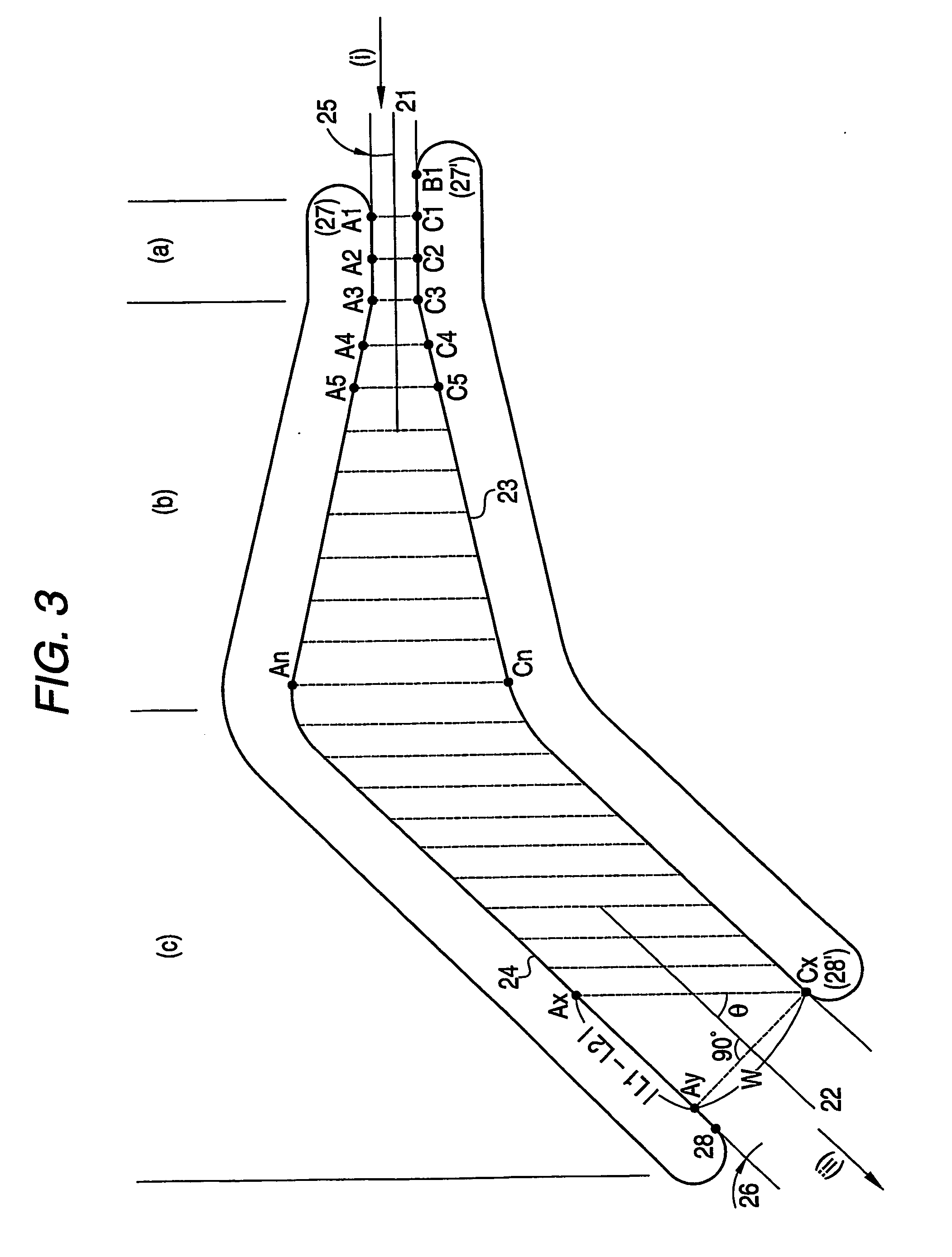
[0225] A PVA film was dipped in an aqueous solution containing 2.0 g / liter of iodine and 4.0 g / liter of potassium iodide at 25° C. for 240 seconds and further dipped in an aqueous solution containing 10 g / liter of boric acid at 25° C. for 60 seconds. Subsequently, the film was introduced into a tenter stretching machine in the form of FIG. 3 and stretched to 5.3 times. Then, the tenter was bent as shown in FIG. 3 with respect to the stretching direction and thereafter, the width was kept constant. The film was dried in an atmosphere at 80° C. and removed from the tenter. The difference in the conveyance speed between right and left tenter clips was less than 0.05% and the angle made by the center line of film introduced and the center line of film delivered to the next step was 46°. Here, |L1−L2| was 0.7 m, W was 0.7 m and a relationship of |L1−L2|=W was established. The substantial stretching direction Ax-Cx at the tent...

example sample 1b

[0228] A polarizing plate with an antiglare and antireflection film was produced by attaching the saponified film of Example Sample 1 in place of “Fujitac (cellulose triacetate, retardation value: 3.0 nm) produced by Fuji Photo Film Co., Ltd.” in the production of the polarizing plate having an absorption axis inclined at 45° of Example Sample 1A. Using this polarizing plate, a liquid display device where the antiglare and antireflection layer was disposed as the outermost layer was produced. As a result, similarly to Example Sample 1, excellent contrast was revealed due to no reflection of external light and despite a high image quality-type high refinement liquid crystal display having microsize picture elements, glaring and blurring of letters did not occur, black was not loosened, and a display device having high visibility and good appearance was obtained.


PUM

PropertyMeasurementUnit
thicknessaaaaaaaaaa
thicknessaaaaaaaaaa
thicknessaaaaaaaaaa

Abstract

To provide an antiglare and antireflection film having sufficiently high antireflection performance and at the same time, having excellent image display quality. An antiglare and antireflection film comprising a transparent support and at least one antiglare hard coat layer, wherein the at least one antiglare hard coat layer comprises a first light-transmissive particle having an average particle size of 60% to less than 95% based on the thickness of the antiglare hard coat layer, and a second light-transmissive particle having an average particle size of 105% to less than 140% based on the layer thickness.

Description

TECHNICAL FIELD [0001] The present invention relates to an antireflection film having antiglare property, and a polarizing plate and a display device using the same. BACKGROUND ART [0002] The antiglare and antireflection film has a function of reducing the reflectance using the scattering of light by surface protrusions and the thin film interference and in an image display device such as cathode ray tube display device (CRT), plasma display panel (PDP), electroluminescence display (ELD) and liquid crystal display device (LCD), this film is generally disposed on the outermost surface of a display so as to prevent the reduction of contrast due to reflection of external light, or prevent the entering by reflection of an image. [0003] As for the design of surface shape of the antiglare layer, JP-A-8-309910 (the term “JP-A” as used herein means an “unexamined published Japanese patent application”) discloses a technique for attaining both antiglare property and transmittance by setting ...

Claims


Application Information

Patent Timeline
Patent Type & Authority Applications(United States)
IPC IPC(8): G02B1/11G02B5/02
CPCG02B1/111G02B5/0278G02B5/0226G02B1/11G02B5/02
Inventor MATSUNAGA, NAOHIRO
Owner FUJIFILM CORP
Why Eureka
Try Eureka