Deterministic jitter equalizer

a jitter equalizer and jitter technology, applied in the field of deterministic jitter equalizer, can solve the problems of reduced margin between symbol levels, insufficient bandwidth, and errors often occurring during data transmission, and achieve the effect of improving the phase noise of the recovered clock signal and being easy to implemen

Active Publication Date: 2005-07-14
CALIFORNIA INST OF TECH
View PDF3 Cites 56 Cited by
  • Summary
  • Abstract
  • Description
  • Claims
  • Application Information

AI Technical Summary

Benefits of technology

[0020] Many benefits are achieved by way of the present invention over conventional techniques. For example, the methods provide for a deterministic jitter equalizer that is relatively easy to implement in existing data receivers. The deterministic jitter equalizer can be scaled and delay optimized for a variety of deterministic jitter sources, including bandwidth limited channels and symbol reflections in transmission lines. Compensating for deterministic jitter in a clock recovery circuit can improve the phase noise of the recovered clock signal. The deterministic jitter equalizer can ensure that data transitions occur more uniformly relative to a predetermined threshold. A corresponding data eye for deterministic equalized data can show a greater margin, or eye opening. Depending on the embodiment, one or more of these benefits can be achieved.

Problems solved by technology

However, if the symbol rate exceeds the bandwidth of any component in the communication link, errors often occur during the data transmission.
Insufficient bandwidth does not allow the signal to make a complete transition within a symbol period and the margin between symbol levels is reduced.
Furthermore, insufficient bandwidth causes the symbol timing at the receiver to deviate from the timing at the transmitter.
The total deviation, called timing jitter, is exacerbated in high-speed communication systems and jitter requirements are increasingly restrictive.
Furthermore, the signal is attenuated during transmission over the channel, reducing the signal-to-noise ratio and limiting the sensitivity of the receiver.
The timing jitter is often most severe after this amplification at the input to the clock and data recovery (CDR) circuit.
Therefore, the data jitter deviations translate to phase noise in the recovered clock and consequently sampling uncertainty in the data eye.
Therefore, timing jitter of the data disturbs the oscillator and the sampling uncertainty is increased.

Method used


Image

  • Deterministic jitter equalizer
  • Deterministic jitter equalizer
  • Deterministic jitter equalizer

Examples


Embodiment Construction

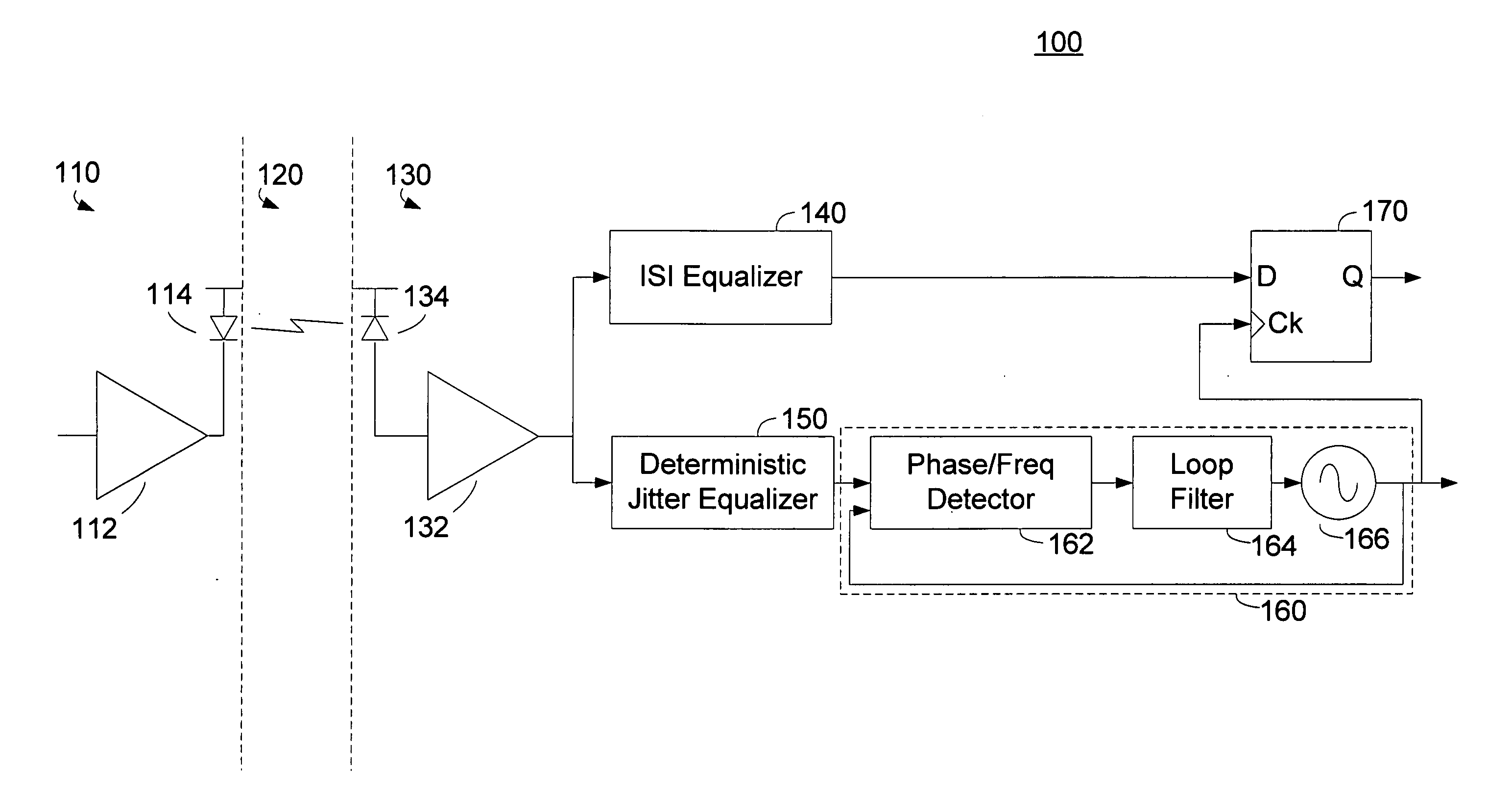
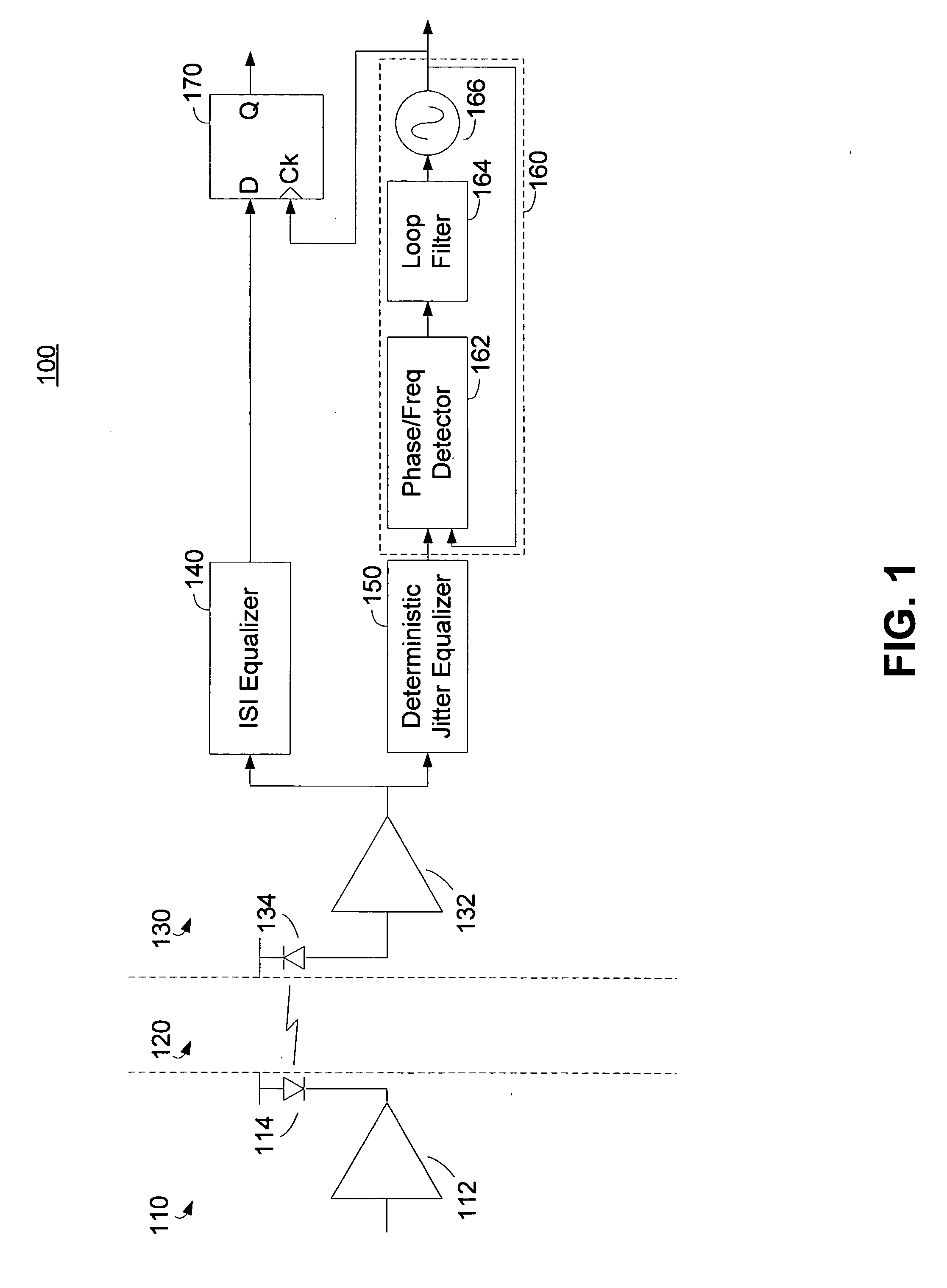
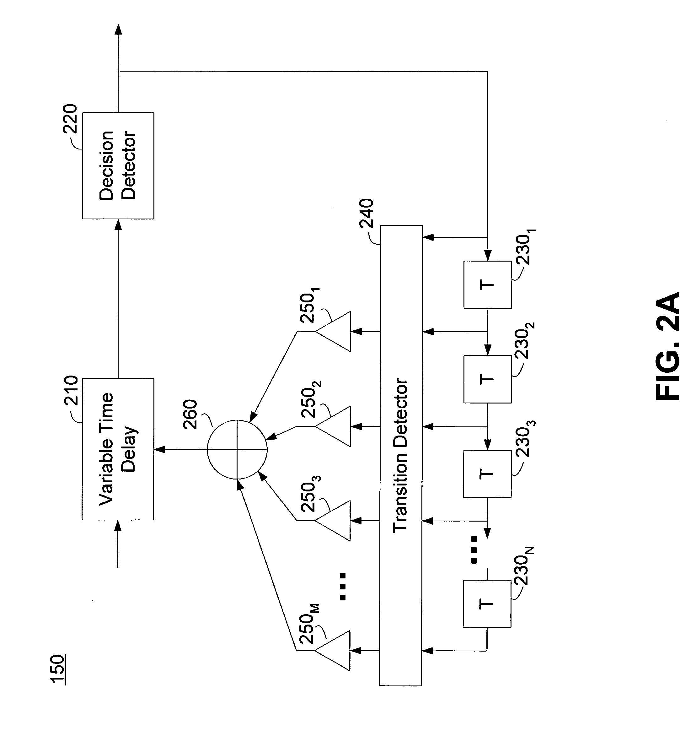
[0040] A deterministic jitter equalizer and a method of equalizing deterministic jitter are disclosed. The deterministic jitter equalizer can be configured to vary a time delay in a received signal path based at least in part on the state of previously received data. In one embodiment, the deterministic jitter equalizer can determine whether one or more data transitions occurred in one or more previously received data bits or symbols and adjust the delay in the signal path based in part on a position of the one or more data transitions. The deterministic data equalizer can be configured to adjust the delay to match the delay introduced by data dependent jitter sources.

[0041]FIG. 1 is a functional block diagram of an embodiment of a serial data communication system 100 incorporating the deterministic jitter equalizer. The serial data communication system 100 can include a transmitter 110 communicating over a channel 120 to a receiver 130. In the embodiment shown in FIG. 1, the trans...


PUM


Abstract

An equalizer for serial data communications can be configured to compensate for the effects of deterministic jitter. The equalizer can be configured to compensate a received serial data stream for the effects of data-dependent jitter as well as duty cycle distortion jitter. The equalizer can be configured to determine the value of one or more previously received symbols and compare them to a recovered symbol. The equalizer can adjust a variable delay positioned in the serial data path to introduce a delay into the data path that is based in part on the received data stream. The equalizer can be configured to vary the delay when any of the one or more previously received symbols is different from the recovered symbol, and can be configured to maintain a constant delay if the one or more previously received symbols is the same as the recovered symbol.

Description

CROSS-REFERENCES TO RELATED APPLICATIONS [0001] This application claims the benefit of U.S. Provisional Application No. 60 / 529,871, filed Dec. 16, 2003, entitled DETERMINISTIC JITTER EQUALIZER; which is hereby incorporated herein by reference in its entirety.BACKGROUND OF THE DISCLOSURE [0002] The present invention relates to electronic data communications. More particularly, the disclosure relates to timing jitter and compensating for timing jitter in a high speed communication link. [0003] Signal integrity issues such as timing jitter are at the forefront of high-speed digital design for communication applications. Electronic circuit speeds are overwhelming the legacy channels that traditionally could be treated as ideal. In high-speed data circuits, the channel behavior is typically compensated appropriately to enable the highest information capacity. Noise considerations dictate the choice of equalization technique. [0004] In serial communications, data encoded as symbols are tr...

Claims


Application Information

Patent Timeline
Patent Type & Authority Applications(United States)
IPC IPC(8): H03H11/26H04B1/10H04L1/20H04L7/033
CPCH03H11/265H04L7/0337H04L1/205
Inventor BUCKWALTER, JAMESHAJIMIRI, SEYED ALIANALUI, BEHNAM
Owner CALIFORNIA INST OF TECH
Why Eureka
Try Eureka