Flow rate measuring method and flowmeter, flow rate measuring section package used for them and flow rate measuring unit using them, and piping leakage inspection device using flowmeter

a flow rate and flowmeter technology, applied in fluid-tightness measurement, liquid/fluent solid measurement, instruments, etc., can solve the problems of reducing measurement sensitivity, increasing the ratio of distinguishable flow rate difference, and increasing flow rate measurement. achieve the effect of satisfying precision and sensitivity

Inactive Publication Date: 2005-07-21
SAN-A
View PDF2 Cites 7 Cited by
  • Summary
  • Abstract
  • Description
  • Claims
  • Application Information

AI Technical Summary

Benefits of technology

[0011] Therefore, an object of the present invention is to provide a method of measuring a flow rate and a flowmeter in which the flow rate can be measured with satisfactory precision and sensitivity over a broad flow rate range from a trace flow rate region to a comparatively large flow rate region.

Problems solved by technology

However, in the flow rate sensor, the change of the output of the electric circuit with respect to a flow rate change is reduced in a region in which a flow rate value is a trace amount of 1 milliliter / h or less, there is a problem that an error of the flow rate measurement increases (i.e., a ratio of a distinguishable flow rate difference increases during measurement, and measurement sensitivity drops).
However, in a case where the sensor is used in the detection of the oil leakage, when the flow rate value is, for example, 3 milliliters / h or more, the change of the output of the electric circuit with respect to the flow rate change is small, and therefore there is a problem that the error increases in a large flow rate value region (i.e., the ratio of the distinguishable flow rate difference increases during the measurement, and the measurement sensitivity drops).
Micro cracks are generated in the piping by time degradation before long, and there is a very strong possibility that oil leakage is generated from the cracks.
In this situation, surrounding environment pollution is caused, and enormous expenses are required for recovery.
However, in these methods, an operation for sealing all openings in the piping with putty or the like is required prior to the leakage inspection operation, an operation for extracting all the oil in the piping is required, and the operations are very troublesome.
Additionally, when the openings are not completely sealed, the leakage detected in these methods does not necessarily reflect actual oil leakage based on the cracks in the piping, and it cannot be said that precision is high for labors of the inspection operation.

Method used


Image

  • Flow rate measuring method and flowmeter, flow rate measuring section package used for them and flow rate measuring unit using them, and piping leakage inspection device using flowmeter
  • Flow rate measuring method and flowmeter, flow rate measuring section package used for them and flow rate measuring unit using them, and piping leakage inspection device using flowmeter
  • Flow rate measuring method and flowmeter, flow rate measuring section package used for them and flow rate measuring unit using them, and piping leakage inspection device using flowmeter

Examples


Embodiment Construction

[0096] Embodiments of the present invention will be described hereinafter with reference to the drawings. Corresponding parts, members, or devices over the drawings are denoted with the same reference numerals.

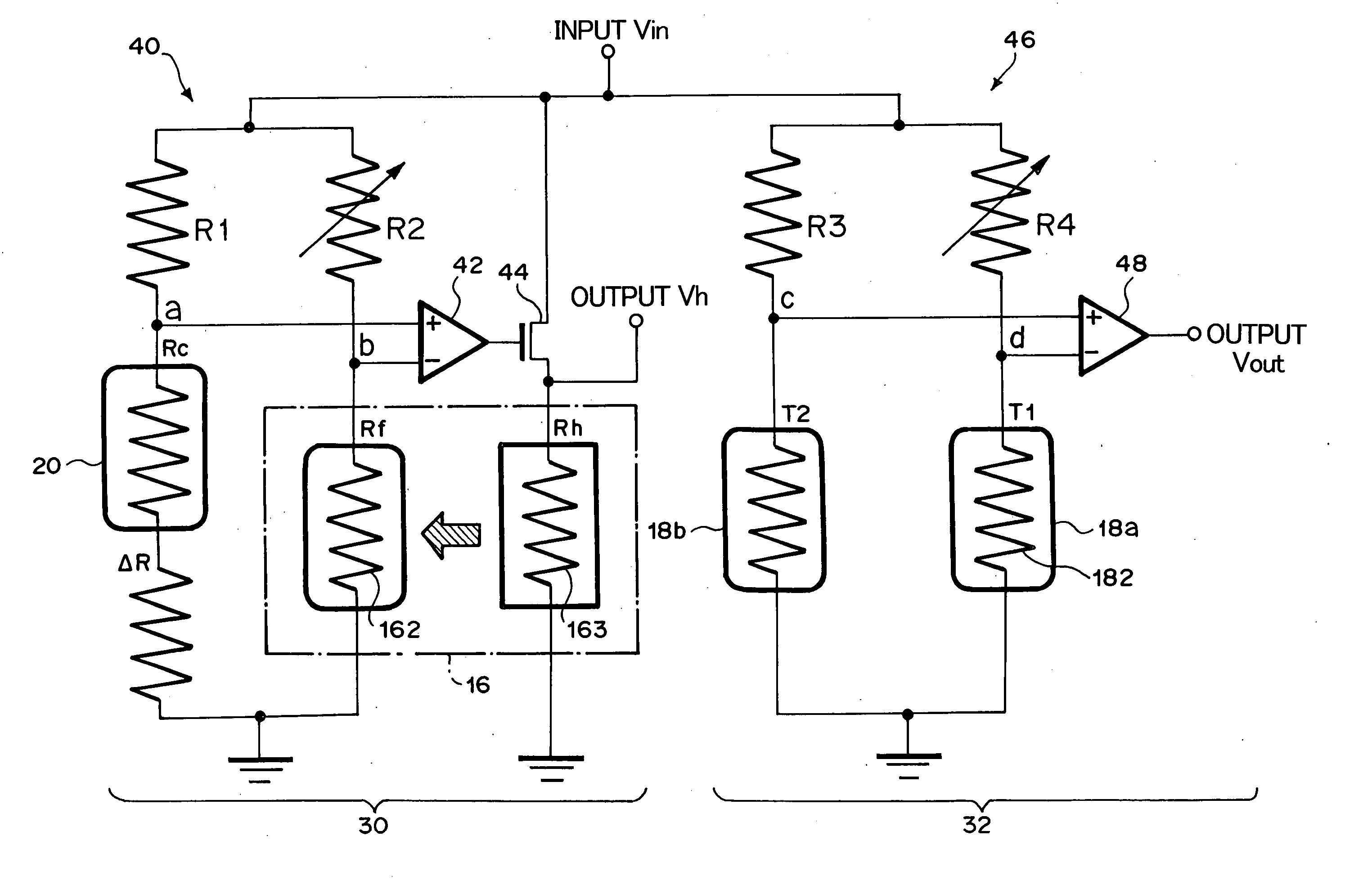
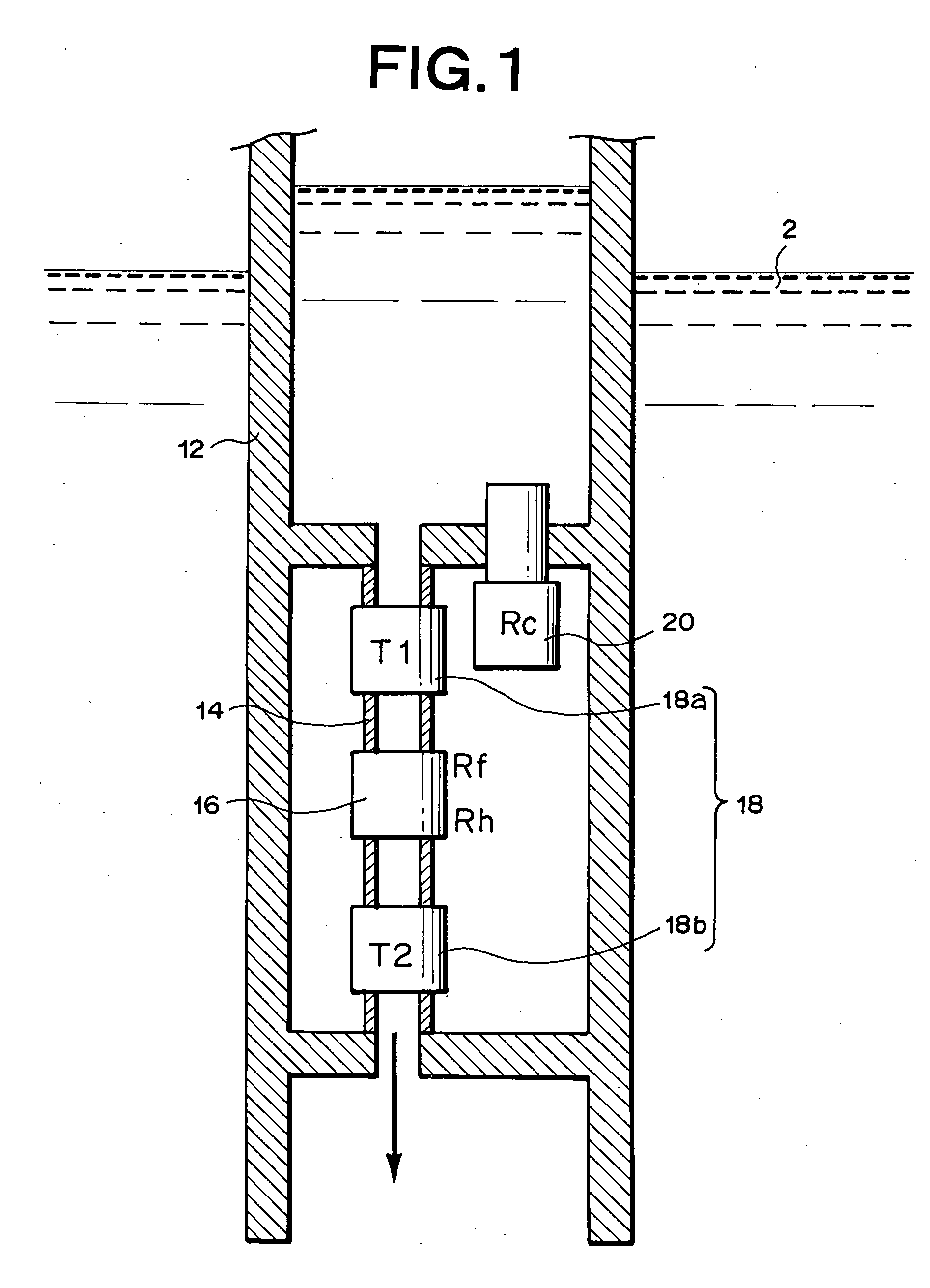
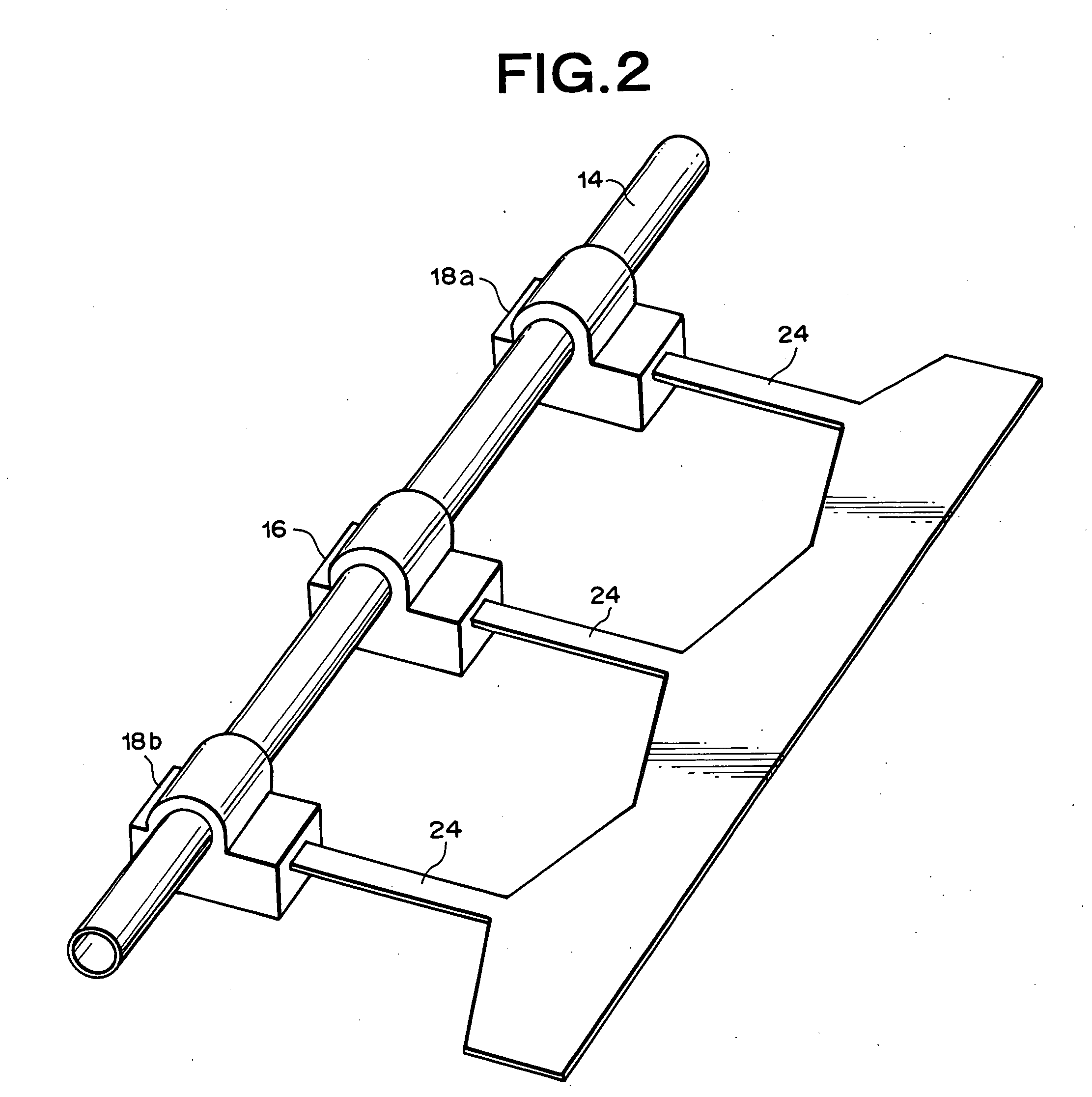
[0097]FIG. 1 is a schematic sectional view showing an embodiment of a flowmeter according to the present invention, for use in performing a method of measuring a flow rate according to the present invention, FIG. 2 is a partial perspective view showing a structure of the flowmeter, FIGS. 3 and 4 are partial sectional views of FIG. 2, FIG. 5 is a block diagram showing a flow rate measuring system of the present embodiment, and FIG. 6 is a diagram showing a circuit constitution for detecting a flow rate of the system. The present embodiment is used in detecting a leakage of a liquid in a tank from the tank.

[0098] As shown in FIG. 1, a lower part of a cylindrical measuring tube 12 is immersed in an in-tank liquid (inflammable liquids such as gasoline, light oil, and kerosene) 2...


PUM


Abstract

Measurements are obtained by a computing unit based on an output Vh from an indirectly-heated constant-temperature controlling flow rate measuring section (16) and an output Vout from a two-constant-point temperature difference detecting flow rate measuring sections (18a, 18b). In the flow rate measuring section (16), a heating element (163) is feedback-controlled based on a detected temperature by a heat sensing element (162) to obtain an output Vh based on the feedback-controlled condition. An output Vout is obtained from flow rate measuring sections (18a, 18b) based on the detected temperature difference between a heat sensing element (182) disposed on the liquid-flow-direction upstream side of the flow rate measuring section (16) and a temperature sensing element disposed on the downstream side. A computing unit outputs as a measurement a flow rate obtained based on the output Vh in a flow rate region where a flow rate is larger than a predetermined boundary flow rate, and outputs as a measurement a flow rate obtained based on the output Vout in a flow rate region where it is less than a boundary flow rate. Accordingly, a flow rate is measured with good precision and sensitivity over a wide flow rate range from a trace-amount flow rate region to a comparatively large flow rate region.

Description

TECHNICAL FIELD [0001] The present invention belongs to a fluid flow rate detection technique, and relates particularly to a method of measuring a flow rate of a fluid flowing through a fluid channel, and a flowmeter for use in the method. The present invention also relates particularly to a flow rate measuring section package for measuring a flow rate of a fluid flowing through a fluid channel, and a flow rate measuring unit using the package. Furthermore, the present invention relates to a device or apparatus which inspects a leakage of a liquid from a piping using a flowmeter. The leakage inspection apparatus of the present invention is preferably used, for example, in inspecting a liquid leakage in a piping which pumps out the liquid from a fuel oil tank such as a petroleum tank buried underground or a tank for various types of liquefied chemicals. BACKGROUND ART [0002] Various types of flow rate sensors (or flow velocity sensors) which measure flow rates (or flow velocities) of...

Claims


Application Information

Patent Timeline
Patent Type & Authority Applications(United States)
IPC IPC(8): G01F1/68G01F1/684G01F1/699G01F7/00G01M3/28
CPCG01F1/68G01F1/6847G01M3/2807G01F7/00G01F1/699G01F1/692G01F1/696G01F1/698
Inventor KOIKE, ATSUSHIKAWANISHI, TOSHIAKINAKAMURA, TOSHIMITAKAHATA, TAKAYUKIYAMAGISHI, KIYOSHI
Owner SAN-A
Why Eureka
Try Eureka