Micropump check valve and method of manufacturing the same

a technology of check valve and micropump, which is applied in the direction of positive displacement liquid engine, piston pump, liquid fuel engine, etc., can solve the problems of changing the properties of the components of the fluid, affecting the flow of the fluid, and threatening the dissolution of adhesives into the fluid, so as to enhance reliability and improve reliability.

Inactive Publication Date: 2005-07-21
PANASONIC CORP
View PDF3 Cites 45 Cited by
  • Summary
  • Abstract
  • Description
  • Claims
  • Application Information

AI Technical Summary

Benefits of technology

[0015] In this case, it is suitable to constitute the valve forming member and the valve receiving member with the same material, or to bond the valve forming material and the valve receiving material by a solid phase diffusion bonding method. By constituting with the same material, bonding can be performed extremely satisfactorily with the solid phase diffusion bonding method, and electrolytic etching that occurs when bonding different types of metal does not occur. Further, by performing pressurization by pressing process, the process of applying pretension can be carried out easily and satisfactorily.
[0016] Additionally, by forming a depression on at least one of a location facing a supporting part of the valve part and a part of the valve receptor in the valve receiving member, or by interposing a spacer material between the valve forming member and the valve receiving member, so that at least one of the valve part and the supporting part is spaced apart from the valve receiving member during bonding. Thus, the valve part and the supporting part thereof can be reliably prevented from fixing to the valve receiving member during bonding, while still satisfactorily bonding the valve forming member and the valve receiving member, thereby further enhancing reliability.
[0017] According to the present invention, after bonding the valve forming member and the valve receiving member, the valve receptor is projected towards the valve part side and pretension is applied, so that the valve forming member and the valve receiving member can be satisfactorily bonded by a solid phase diffusion bonding method and the like using a relatively inexpensive material such as stainless steel without using an adhesive. Thus, dissolving of adhesive and stripping off of adhered portions do not occur, unlike the case where adhesive is used. Further, reduction of pretension does not occur in the annealing state, so that the valve part contacts the valve receptor in a state where pretension has been applied satisfactorily, thereby enhancing reliability.

Problems solved by technology

Further, in the case that each members are adhered using an adhesive, if a component for dissolving the adhesive such as alcohol is contained in a fluid supplied by the micropump, the adhesive is threatened to dissolve into the fluid, thereby changing the properties of the components of the fluid, or stripping off the adhered portions.
Further, the adhesive may remain at the interface between the adhered parts during adhesion thus worsening the flow of the fluid.
Furthermore, since the adhered region during adherence is unstable, bonding with high accuracy cannot be achieved.
Additionally, in the micropump shown in JP-A 04-63973, when providing the projection of polymeric material at the valve part of the substrate made of silicon, it is required to perform dry etching on the silicon substrate and form the projection by screen printing in an aligned condition with high accuracy, which is troublesome and time consuming because of the complicated steps.
Moreover, since the dry etching apparatus is expensive and the silicon material itself is expensive, the manufacturing cost becomes extremely high.
As such bonding method, bonding the valve forming material and the valve receiving member under high temperature by a method like diffusion bonding may be conceived, but with such method, a problem arises that tension may be lost in the annealed state.
Therefore, in order to prevent the problem, it is required to perform bonding using adhesive under a relatively low temperature or bonding at a limited bonding region excluding the portion provided with pretension, which is, however, followed by another problem that when using the adhesive, the adhesive dissolves into the fluid, the adhered portion may be stripped off, and the flow of the fluid worsens.
Further, when bonding is performed for a limited bonding region, the diffusion bonding method cannot be employed, thus necessitating the use of ultrasonic welding or laser welding, which causes a problem to arise that distortion occurs at the border between the bonded portion and the non-bonded region, rendering it impossible to perform bonding with high accuracy.

Method used


Image

  • Micropump check valve and method of manufacturing the same
  • Micropump check valve and method of manufacturing the same
  • Micropump check valve and method of manufacturing the same

Examples


first embodiment

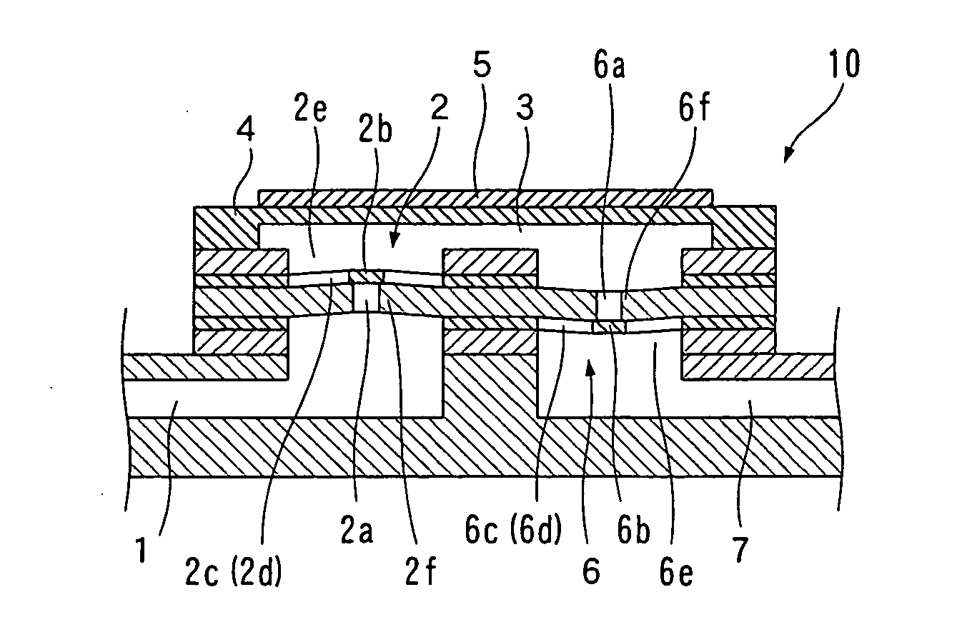
[0033] First, the micropump check valve manufactured by the method of manufacturing micropump check valve according to the present invention, and a configuration of the micropump using such check valve will be explained using FIG. 1 and FIG. 2.

[0034] As shown in FIG. 1, the micropump 10 includes an inflow path 1 for introducing fluid (e.g., alcohol) gas or a mixture of the above to be delivered, a suction side check valve 2 arranged connected to the inflow path 1, a pressure chamber 3 into which the fluid from the inflow path 1 flows by way of the suction side check valve 2, a vibrating plate 4 vibrated to apply pressure to the pressure chamber 3, a piezoelectric element 5 for vibrating the vibrating plate 4, a discharge side check valve 6 arranged and connected to the pressure chamber 3, and an outflow path 7 for discharging the fluid from the pressure chamber 3 by way of the discharge side check valve 6. Here, the suction side check valve 2 and the discharge side check valve 6 are...

third embodiment

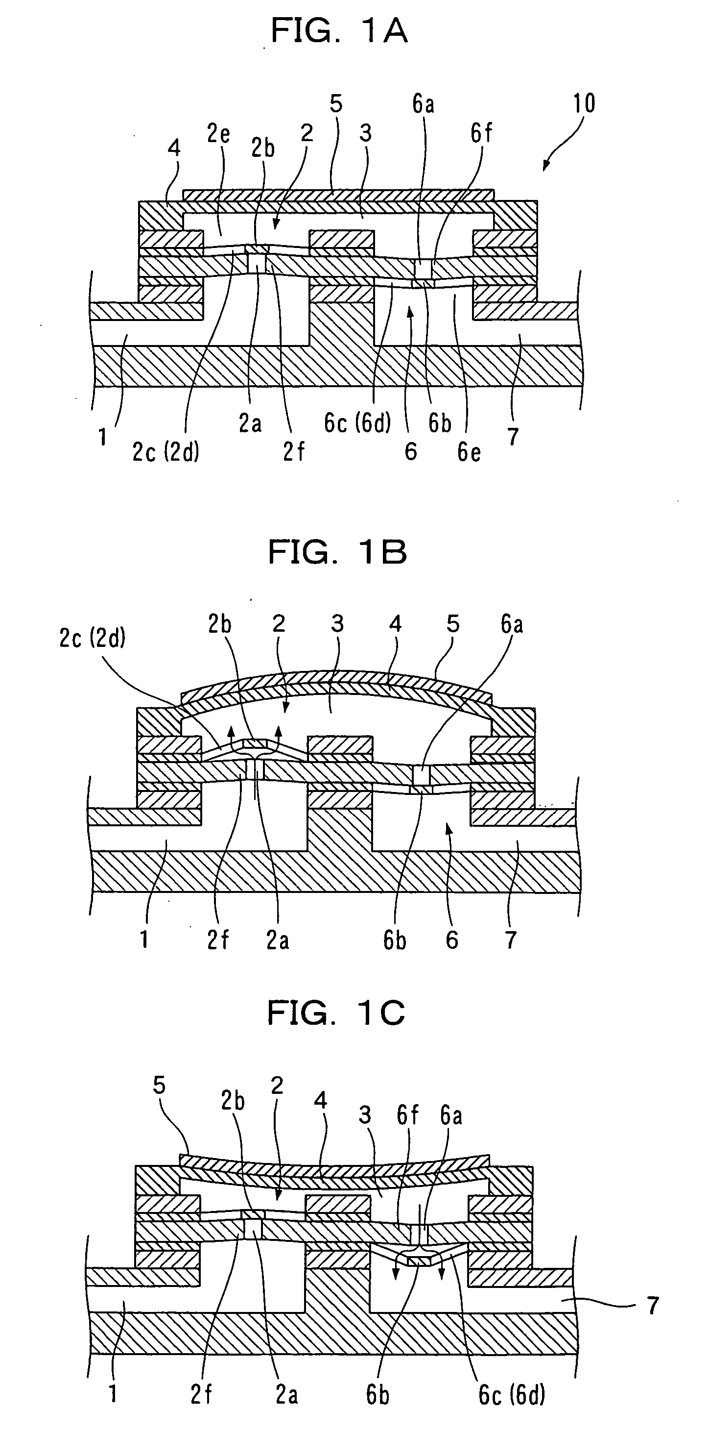
[0058] As in a third embodiment shown in FIG. 9, the hole 2a of the valve receiving member on the side distant from the check valves 2 and 6 may also be formed in accordance with the diameter of the punch indenter 50 so as to push out only one valve receiving member by the punch indenter 50 of the pressing device, in which case, the number and thickness of the plate materials to be deformed by the pressing process are reduced, and thus has an advantage of making the pressing force by the punch indenter 50 of the pressing device small and using an inexpensive pressing device.

fourth embodiment

[0059] Further, FIG. 10 and FIG. 11 show the present invention, and FIG. 12 and FIG. 13 show a fifth embodiment of the present invention.

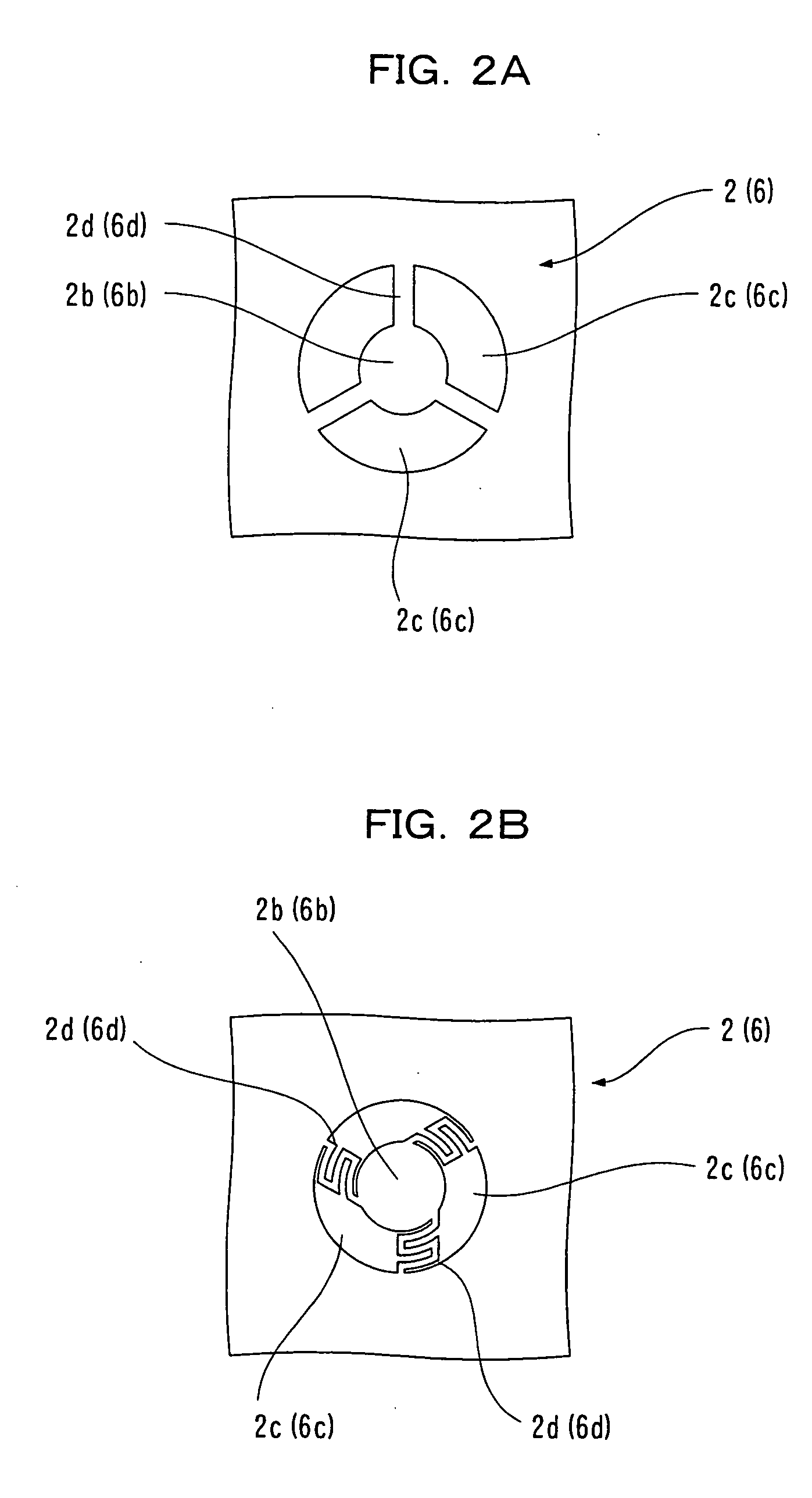
[0060] As shown in FIG. 10 and FIG. 11, in the fourth embodiment, the check valves 2 and 6 are configured by five plate materials 11, 12, 13, 15 and 16, and the valve parts 2b and 6b, the supporting parts 2d and 6d of both check valves 2 and 6, and the passing hole 6c are formed on the third plate material 13 at the intermediate position.


PUM

PropertyMeasurementUnit
temperatureaaaaaaaaaa
pressureaaaaaaaaaa
displacementaaaaaaaaaa

Abstract

The invention provides a method capable of manufacturing a micropump check valve, inexpensively and without much trouble or time, which does not cause disadvantages even if a material that dissolves an adhesive is contained in the fluid, and which allows bonding with high accuracy. After a valve forming member and a valve receiving member are bonded, a valve receptor is projected towards a valve part and pretension is applied. Thus, the valve forming member and the valve receiving member can be satisfactorily bonded through a solid phase diffusion bonding method and the like using a relatively inexpensive material, such as stainless steel, without using an adhesive, and the pretension is not reduced when in the annealing state.

Description

BACKGROUND OF THE INVENTION [0001] 1. Field of the Invention [0002] The present invention relates to a micropump serving as a small apparatus for supplying small amounts of fluid used in a fuel cell, medical equipments, a chemical analyzer, a microreactor, a biochemical chip and the like, and particularly relates to a method of manufacturing a check valve for preventing back flow of the fluid in this micropump. [0003] 2. Description of the Related Art [0004] In a micropump for delivering small amounts of fluid, a check valve is often used to prevent back flow of the fluid. Under constraints of smallness and thinness, the check valve is required to be configured that a valve part has pretension so as to contact a valve receptor while applying urging force thereto so that the valve part satisfactorily seals the valve receptor to prevent the back flow of the liquid when only a force smaller than a constant pressure is acting. [0005] The following patent documents disclose a mechanism (...

Claims


Application Information

Patent Timeline
Patent Type & Authority Applications(United States)
IPC IPC(8): B81B3/00F04B43/02F04B43/04F16K15/14
CPCY10T29/49425F04B43/043F16K15/144Y10T137/7838
Inventor MATSUI, MASATOMOSONE, KOJI
Owner PANASONIC CORP
Why Eureka
Try Eureka