Class-L power-output amplifier

a power-output amplifier and amplifier technology, applied in the field of amplifiers and radio transmitters, can solve the problem of double voltage swing across the antenna, and achieve the effect of efficient battery operation

Inactive Publication Date: 2005-07-21
BAUSOV IGOR +1
View PDF4 Cites 46 Cited by
  • Summary
  • Abstract
  • Description
  • Claims
  • Application Information

AI Technical Summary

Benefits of technology

[0016] An advantage of the present invention is that a radio transmitter is provided for efficient battery operation.
[0017] Another advantage of the pr

Problems solved by technology

The result is a voltage swing across the antenna that is twice that whi

Method used


Image

  • Class-L power-output amplifier
  • Class-L power-output amplifier
  • Class-L power-output amplifier

Examples


Embodiment Construction

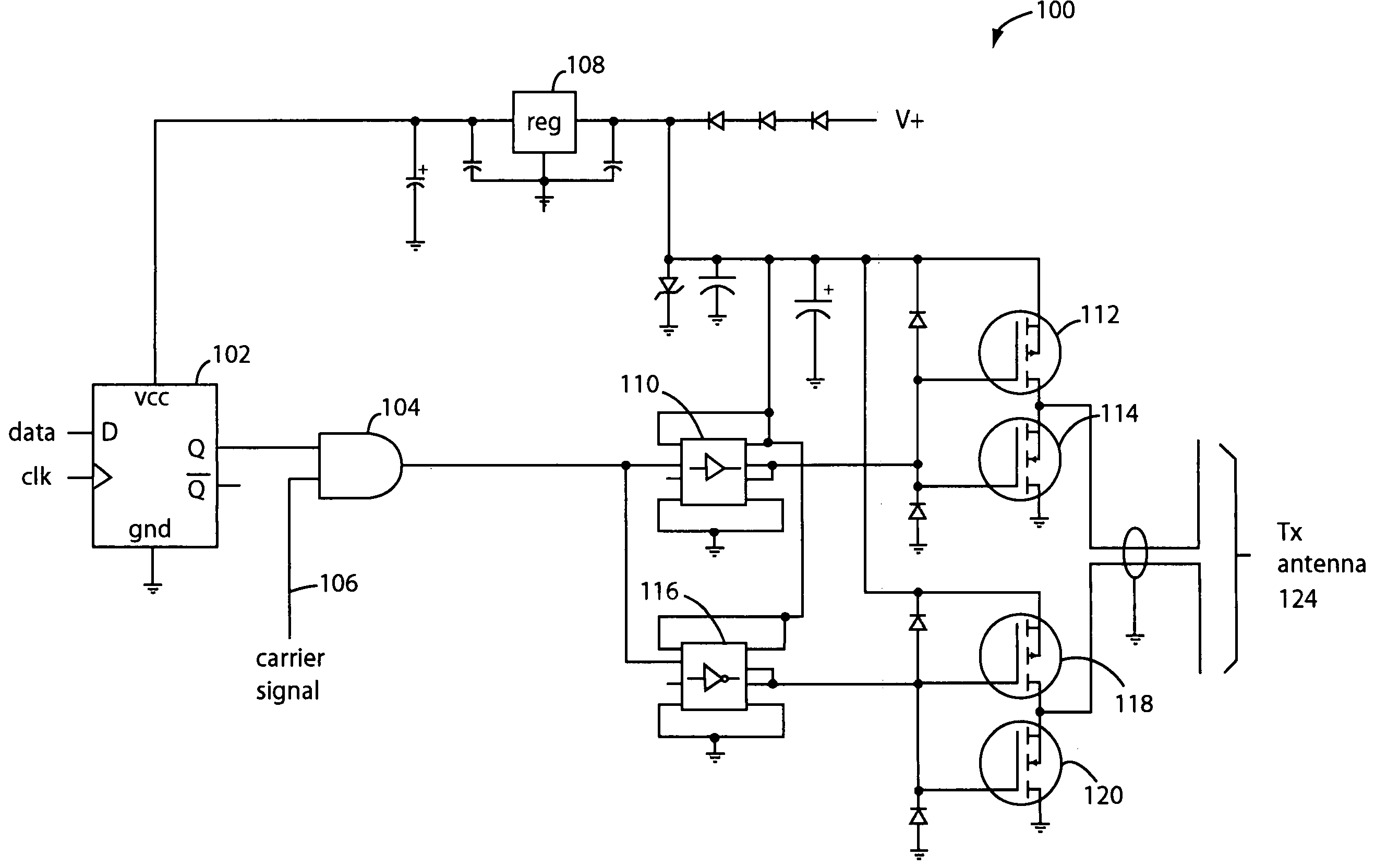
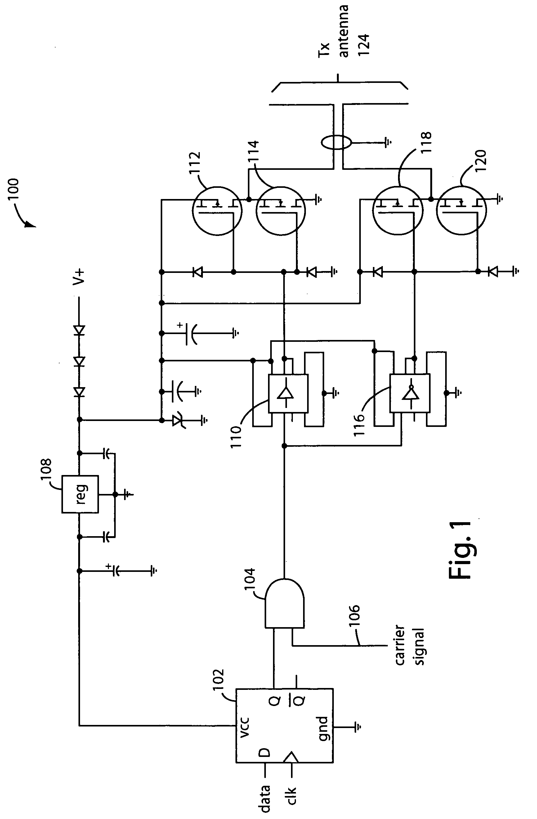
[0021]FIG. 1 illustrates a radio-transmitter power-output amplifier embodiment of the present invention, and is referred to herein by the general reference numeral 100. The amplifier 100 comprises a D-type flip-flop 102 that accepts data input modulation and clocks, a logic AND-gate 104 for gating through a radio carrier input 106 according to the modulation, and a three-terminal voltage regulator 108 that provides operating power to the digital logic. A MOSFET-driver 110 drives a totem-pole arrangement of two power MOSFET's 112 and 114. An inverting MOSFET-driver 116 drives another totem-pole arrangement of two power MOSFET's 118 and 120. Taken altogether, the MOSFET-drivers and the four MOSFET's implement a digital, differential drive radio power output. A balanced transmission line 122 connects the output to an antenna 124.

[0022] In one implementation that worked well, the MOSFET-driver 110 was a Maxim Integrated Products (Sunnyvale, Calif.) MAX4420CSA, the inverting MOSFET-driv...


PUM


Abstract

A radio power output amplifier comprises a balanced radio power output that differentially drives a dipole antenna or other balanced load. One half of the differential power output drives one side of the antenna from ground to the maximum positive rail, while the other half of the differential power output drives the opposite side of the antenna from the maximum positive rail to ground. The result is a voltage swing across the antenna that is twice that which would occur if a single ended output was driving an unbalanced load. Since the power output is the square of the voltage divided by the load impedance, the result is four times the power output.

Description

RELATED APPLICATION [0001] This is a continuation-in-part of U.S. patent application Ser. No. 10 / 046,793, filed Jan. 15, 2002, and titled CLASS-L RADIO POWER-OUTPUT AMPLIFIER, and which was issued a Notice of Allowance on Dec. 27, 2004.1. FIELD OF THE INVENTION [0002] The present invention relates to amplifiers and radio transmitters, and more particularly to methods and circuits for deriving more radio power output to the antenna for a given power supply voltage. 2. DESCRIPTION OF THE PRIOR ART [0003] Much of the power consumed in portable, battery-powered electronic devices is consumed by the output stages. In a transmitter, the radio power output amplifier takes a large percentage of the total power draw. In receivers, its the audio power output amplifier that drives the speakers. [0004] If an amplifier is biased such that 360° of the signal gets amplified through, the amplifier is classified as a Class-A type. Such Class-A biasing helps produce the best signal fidelity and least...

Claims


Application Information

Patent Timeline
IPC IPC(8): G01S13/88H01Q9/16H01Q23/00H03F3/30
CPCG01S13/885H03F3/3059H01Q23/00H01Q9/16
Inventor BAUSOV, IGORSTOLARCZYK, LARRY G.
Owner BAUSOV IGOR
Why Eureka
Try Eureka