Catalyst carrier and method of producing same

Inactive Publication Date: 2005-07-21
IBIDEN CO LTD
View PDF27 Cites 69 Cited by
  • Summary
  • Abstract
  • Description
  • Claims
  • Application Information

AI Technical Summary

Benefits of technology

[0010] It is another object of the invention to propose a catalyst carrier having a large surface area of an a

Problems solved by technology

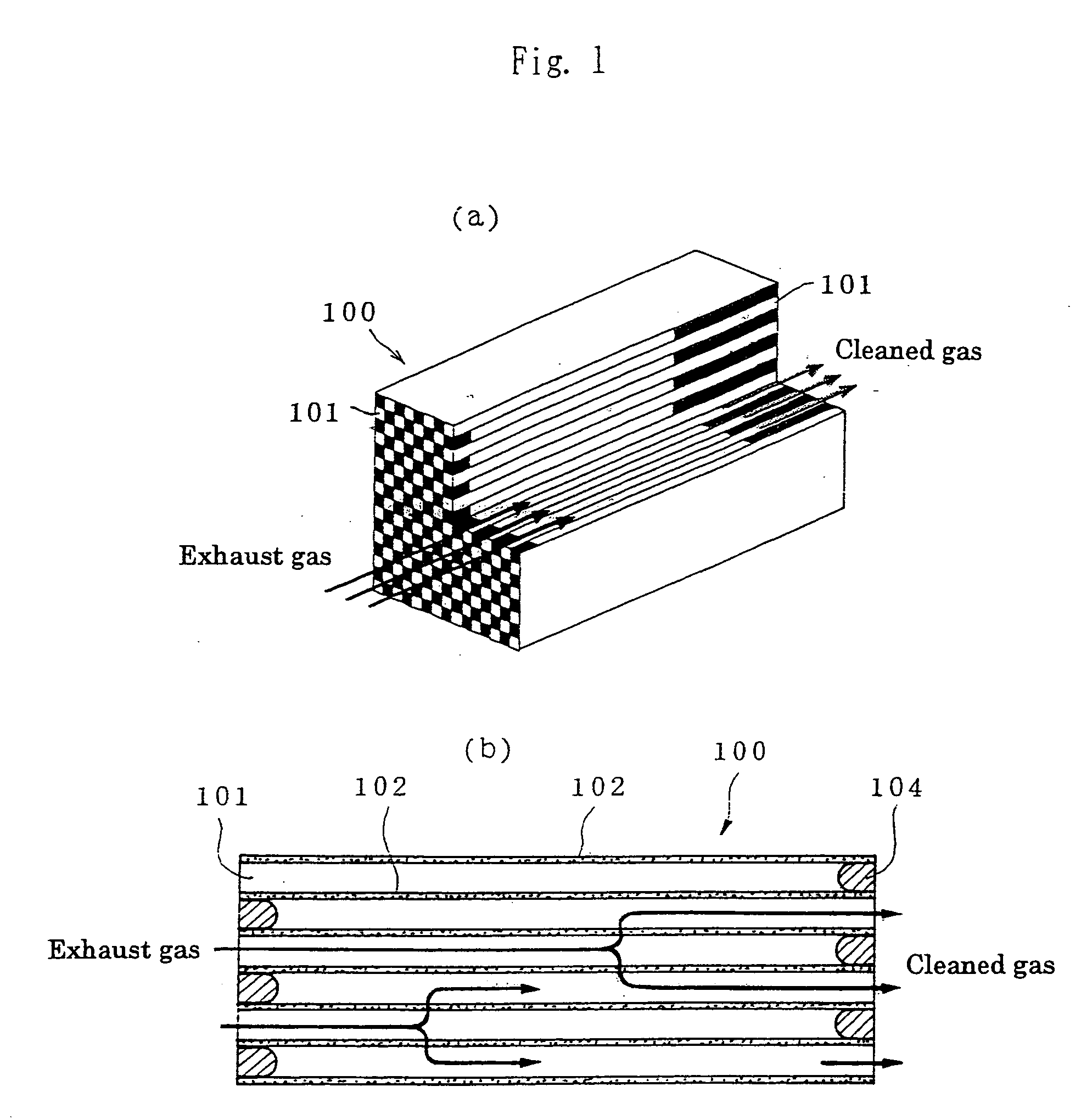
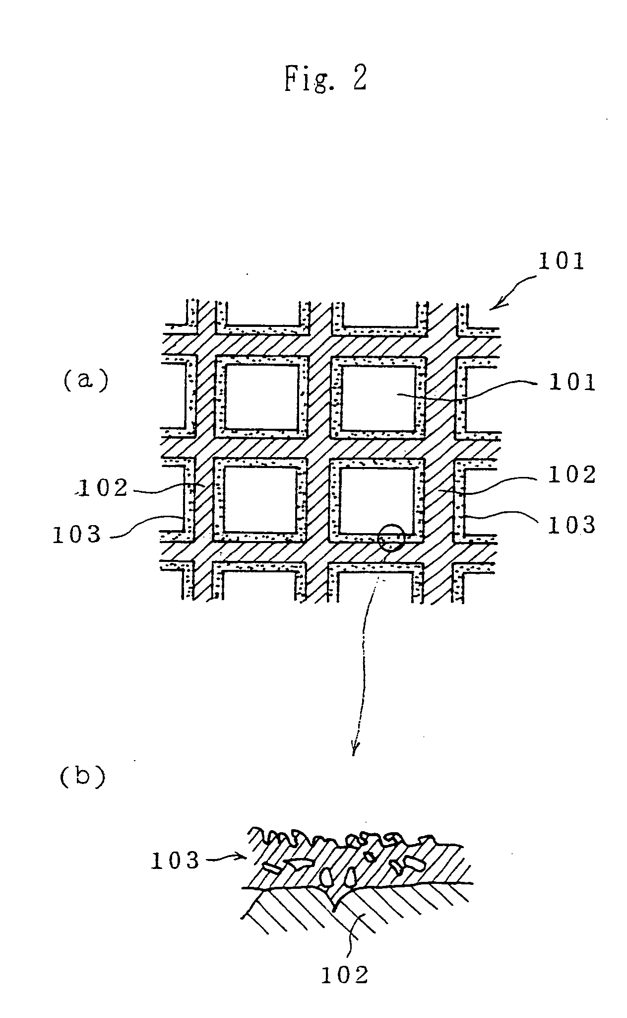
However, the wash coated alumina layer 103 is small in the pore size and porosity and large in the permeation resistance, so that there is a problem that pressure loss considerably increases as compared with the carrier having no alumina layer.
Furthermore, the wash coated alumina layer 103 is poor in the adhesion property because it is uniformly coated onto the surface of the carrier as a filtering wall 102.
And also, there is a problem that the wash coated alumina layer 103 is poor in the heat resistance because such

Method used


Image

  • Catalyst carrier and method of producing same
  • Catalyst carrier and method of producing same
  • Catalyst carrier and method of producing same

Examples


examples

[0085] Catalyst carriers produced under conditions shown in Table 1 (Invention Examples 1, 2, Comparative Example 1) are attached to a particulate filter (DPF) in an exhaust gas cleaning device of a diesel vehicle to conduct a cleaning test. In this test, the pressure loss characteristic, heat resistance and resistance to cleaning are investigated to obtain results as shown in the same table and FIGS. 4 and 5.

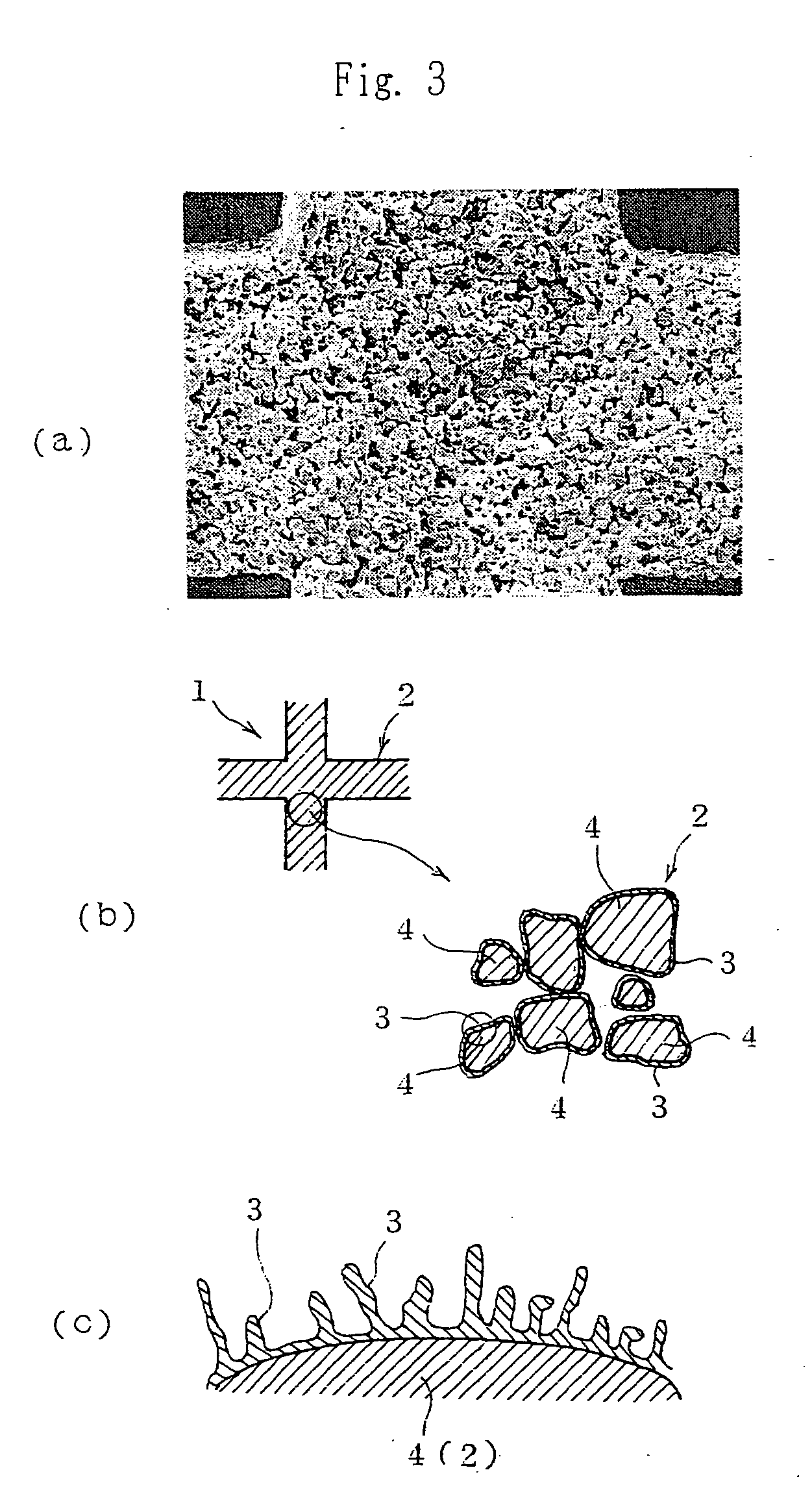
TABLE 1ComparativeExample 1Example 2Example 1Honeycomb carrierSiC filterSiC filterSiC filterAlumina carrying coatimpregnationimpregnationwash coatPretreatment of filternone1100° C., 20 hrnoneSiO2 amount0.2 wt %3 wt %0.2 wt %(Si amount)(0.11 wt %)(1.0 wt %)(0.11 wt %)Al2O3 amount3.2 wt %3.0 wt %3.1 wt %Aluminadiameter10 nm6 nm—thinlength150 nm120 nm—filmfull length / 1520—diameterPressure losscharacteristicHeat resistanceResistance to cleaningno peelingno peeling atalmostat 70 Kg / cm280 Kg / cm2peeling at10 Kg / cm2[0086] a. As shown in FIG. 6, the invention example shows substantial...


PUM

PropertyMeasurementUnit
Lengthaaaaaaaaaa
Lengthaaaaaaaaaa
Lengthaaaaaaaaaa

Abstract

A catalyst carrier which comprises particles of a silicon-containing ceramic material. Each of these particles is covered by a film of alumina on which a noble metal is carried.

Description

CROSS-REFERENCE TO RELATED APPLICATIONS [0001] The present application is a continuation of U.S. patent application Ser. No. 09 / 926,795, filed Dec. 20, 2001, the entire disclosure whereof is expressly incorporated by reference herein, which is a U.S. National Stage of International Application PCT / JP00 / 04084, filed Jun. 22, 2000, which claims priority under 35 U.S.C. § 119 of Japanese Patent Application No. 11-177503, filed Jun. 23, 1999, and Japanese Patent Application No. 11-280072, filed Sep. 30, 1999. TECHNICAL. FIELD [0002] This invention relates to a catalyst carrier for the purification of an exhaust gas and a method of producing the same, and more particularly proposes a catalyst carrier capable of efficiently conducting oxidation-removal of carbon monoxide (CO) and hydrocarbon (HC) included in the exhaust gas and reducing-removal of nitrogen oxide (NOx) and being small in the pressure loss and having a high gathering efficiency of diesel particulate.BACKGROUND ART [0003] He...

Claims


Application Information

Patent Timeline
IPC IPC(8): B01D53/86B01D53/94B01J21/04B01J21/12B01J21/16B01J27/22B01J27/224B01J27/24B01J32/00B01J35/10B01J37/02B01J37/08
CPCB01D53/945B01D53/9454B01D2255/206B01D2255/20715B01J21/04Y02T10/22B01J27/22B01J35/10B01J37/0215B01J37/0221B01J21/12Y02T10/12
Inventor OHNO, KAZUSHIGEKOMORI, TERUOHASEGAWA, AKIRAKAKUTA, NORIYOSHI
Owner IBIDEN CO LTD
Why Eureka
Try Eureka