
Chemical dispensing system for a portable concrete plant

a concrete plant and chemical technology, applied in adaptive control, computer control, instruments, etc., can solve the problems of inability to accurately dispense concrete, inability to accurately measure the level of fill at the sight gauge, and the tendency to overlook the injection of chemical substances, etc., to achieve the effect of increasing repeatability and dispense more accurately

Inactive Publication Date: 2005-07-21
PORT A POUR
View PDF10 Cites 19 Cited by
  • Summary
  • Abstract
  • Description
  • Claims
  • Application Information

AI Technical Summary

Benefits of technology

[0010] The present invention overcomes the disadvantages and limitations of the prior art by providing a system and method for accurately and repeatably measuring and dispensing chemicals into a batch of concrete. Automated pumping and measuring devices coupled to a computer controller to dispense chemicals into a mixing drum prior to the addition of aggregate and concrete. The pumping and measuring devices are separate and independent devices so that redundant readings ensure that no errors occur during dispensing.
[0012] The advantages of the present invention are that chemicals may be dispensed more accurately than with manual methods. Chemicals may be added to concrete during the mixing stage that is not operator dependent and has increased repeatability from batch to batch. The chemicals may be dispensed over a controlled period of time, allowing a more complete and homogenous mixture. Further, a computer may accurately record and certify the amount of chemicals added to each batch of concrete, providing a record of each batch for certification or other uses. Problems with chemical dispensing can be detected quickly so that batches of concrete are not wasted when a problem occurs. In addition, aggregate and concrete are thoroughly mixed as dry components and are conveyed to a dispensing head which dispenses the dry mixture, water and chemicals. Thorough mixing of the dry components reduces wet mixing and ensures proper mixing in correct proportions.

Problems solved by technology

Because a substandard batch of concrete may mean structural failure of a building or structure, it has become common practice to have a concrete batch plant operator visually verify that the proper amounts of chemical additives have been added to each batch of concrete.
There are several problems with the standard method of chemical measuring and dispensing.
Any manual process is prone to error.
Another problem is that the chemicals may be added at different sequences of the batch preparation, causing a potential for overlooking the injection of a chemical.
Highly viscous chemicals can present another problem in that the level of fill at the sight gauge may not be indicative of what was actually dispensed in the measurement container.
This will leave a false measurement and some question about the integrity of the system.
In some mixing plants, if a batch of concrete is being mixed and a problem occurs with the chemical dispensing, the batch may not be able to be stopped.
A batch that is incorrectly mixed may have to be discarded in its entirety, causing a waste of time and materials.

Method used


Image

  • Chemical dispensing system for a portable concrete plant
  • Chemical dispensing system for a portable concrete plant
  • Chemical dispensing system for a portable concrete plant

Examples


embodiment 100

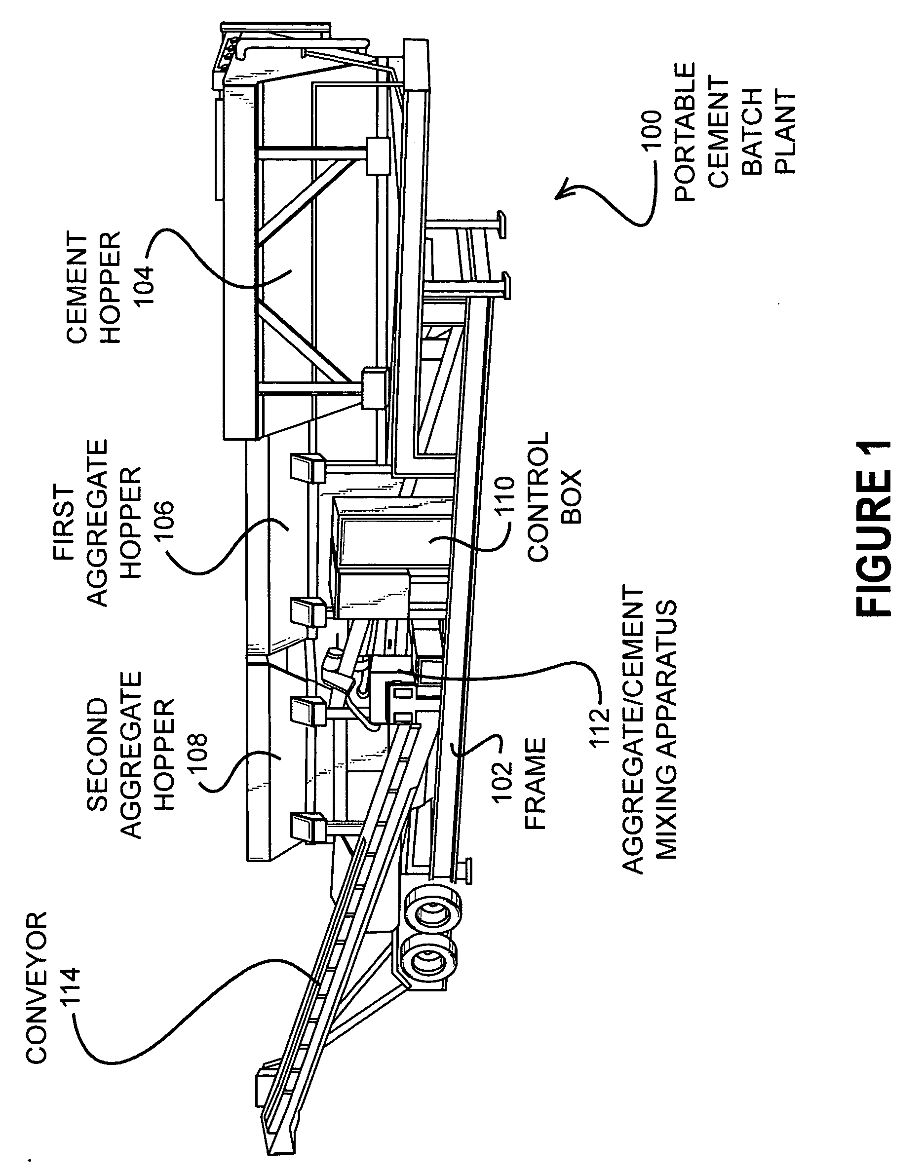
[0019]FIG. 1 illustrates an embodiment 100 of the present invention of a portable cement batch plant that has an automated chemical dispensing system. The frame 102 has several hoppers mounted thereupon: a cement hopper 104, a first aggregate hopper 106, and a second aggregate hopper 108. The control box 110 contains a computerized control system that directs the dispensing of the various dry materials, such as cement, sand, and rock, into a dry mixing apparatus 112 and a conveyor 114. The conveyor 114 may deliver the pre-mixed dry components into a portable concrete mixer truck.

[0020] The plant 100 is designed to charge a concrete mixing truck with a batch of raw materials per a certain specification based on a mix design. The specification may include a certain amount of dry ingredients, such as cement, rock, and sand, as well as certain amounts of water and various chemical agents typically added to concrete mixes. These agents may include water reducing agents, stabilizers, reta...

embodiment 200

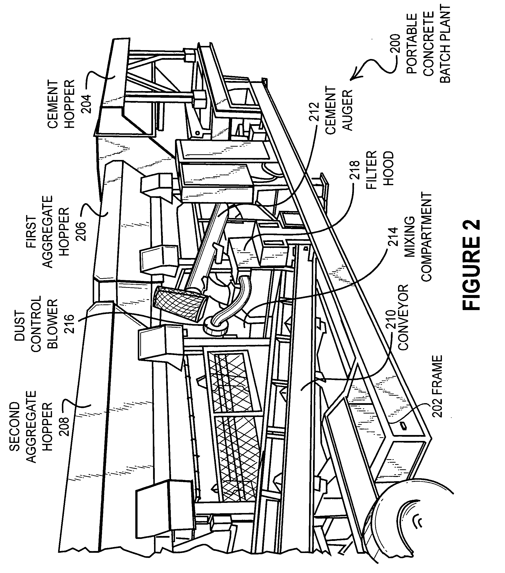
[0026]FIG. 2 illustrates a close up view of an embodiment 200 of a cement batch plant. The frame 202 holds the cement hopper 204, the first aggregate hopper 206, and the second aggregate hopper 208. The delivery conveyor 210 takes the mixed aggregate and cement from the mixing apparatus 214. A cement auger 212 transfers the dry cement from the cement hopper 204 into the mixing apparatus 214. A filtered dust hood 218 is mounted near the exit of the cement auger 212 and has a dust control blower 216 for pulling any excess dust into the filter membrane contained inside the dust hood 218.

[0027]FIG. 3 illustrates a schematic representation of a control system 300 for a typical batch plant. A controller 302 controls a cement hopper 304 and an aggregate hopper 306 to dispense cement 305 and aggregate 307, respectively, into a dry mixing apparatus 308, which dispenses a mixed cement and aggregate 309 into a mixing truck 312. The controller 302 also controls a water / chemical dispensing appar...

embodiment 400

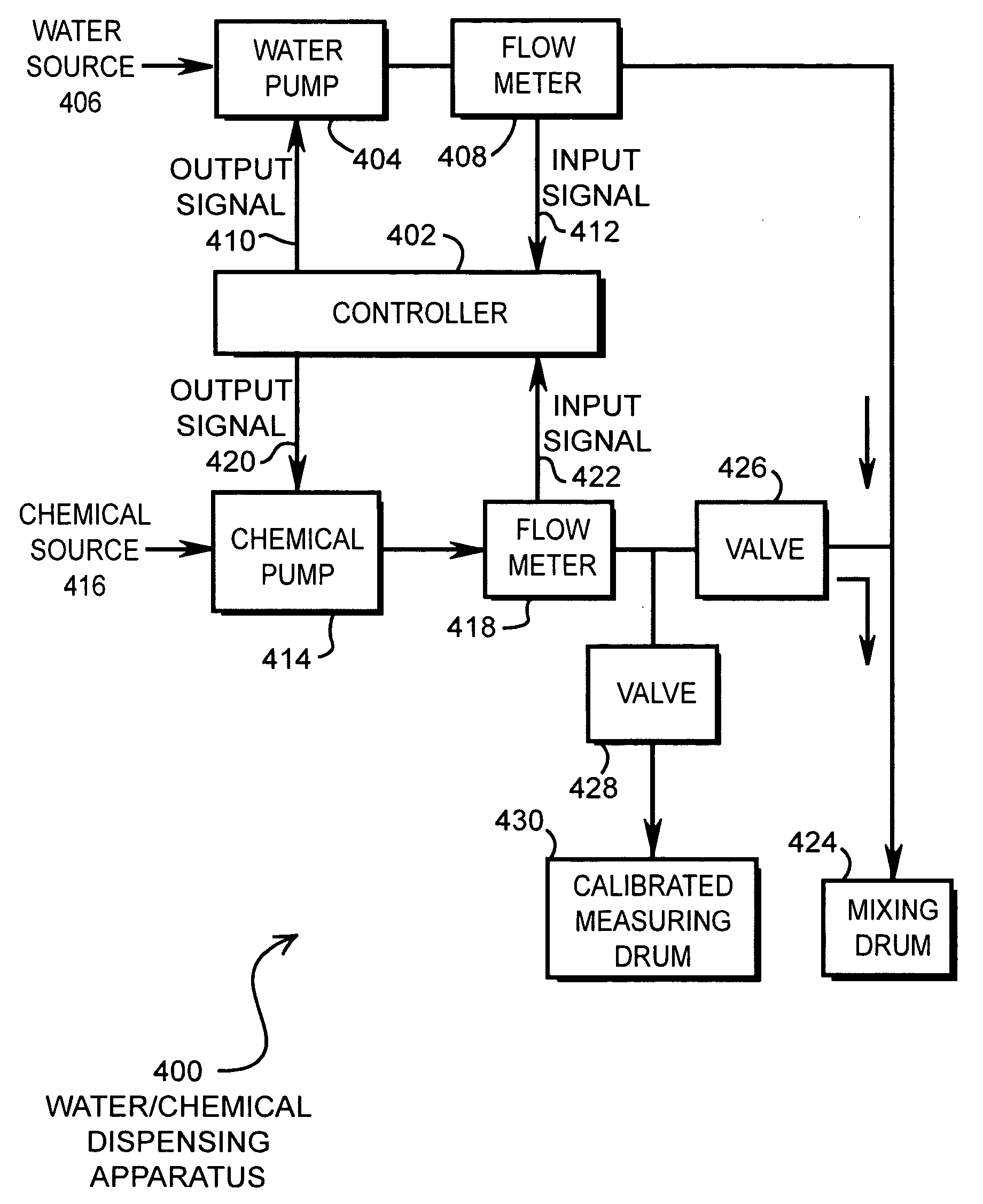
[0033]FIG. 4 illustrates a schematic representation of an embodiment 400 of a water and chemical dispensing apparatus. A controller 402 may control water pump 404 to pump water from a water source 406, through a flow meter 408, and into a mixing drum 424 as might be mounted on a portable mixing truck. Additionally, the controller 402 directs a chemical pump 414 to pump chemicals from a chemical source 416 through a flow meter 418 and into the mixing drum 424. A pair of valves 426 and 428 may be operated to direct the chemical output into a calibrated measurement container 430.

[0034] For both the water circuit and the chemical circuit, the liquid materials are mechanically pumped and the output is monitored by a flow meter. The flow meter serves to measure the proper amount of water or chemical that is dispensed.

[0035] The pumps used in the apparatus 400 may be positive or variable displacement pumps. Sending a stream of pulses to the controller 402 may cause such pumps to pump a ce...


PUM

PropertyMeasurementUnit
diameteraaaaaaaaaa
chemicalaaaaaaaaaa
chemical measuringaaaaaaaaaa

Abstract

A computer controlled pumping and measuring system is used to dispense chemicals into a concrete mix. The redundant use of positive displacement pumps and flow meters ensure that any problems with the chemical dispensing are immediately caught. The computerized control system may be operable to control exact batch configurations of concrete and aggregate in conjunction with the chemical dispensing, as well as provide precise mixture control and recording of the various components.

Description

CROSS REFERENCE TO RELATED APPLICATION [0001] This application is a divisional of U.S. patent application Ser. No. 10 / 738,845 entitled “Portable Concrete Plant Dispensing System” by Neil G. Oberg and Jerome J. Doherty, filed Dec. 17, 2003, which claims the benefit of and priority to U.S. Provisional Patent Application Ser. No. 60 / 436,578 entitled “Chemical Dispensing System” by Neil G. Oberg and Jerome J. Doherty, filed Dec. 23, 2002, the entirety of which is hereby specifically incorporated by reference for all it discloses and teaches.BACKGROUND OF THE INVENTION [0002] a. Field of the Invention [0003] The present invention pertains to concrete mixing plants and specifically to a chemical dispensing apparatus of a concrete mixing plant. [0004] b. Description of the Background [0005] Concrete batch plants measure and dispense cement, aggregate, and water into mixing drums. Often, the mixing drums are mounted on a truck for delivery at a jobsite. In many cases, special chemicals are ...

Claims


Application Information

Patent Timeline
Patent Type & Authority Applications(United States)
IPC IPC(8): B01F15/00B28B7/02B28C7/04
CPCB01F15/00954B28C7/0418B28B7/02B01F15/0479B01F35/181B01F35/883
Inventor OBERG, NEIL G.DOHERTY, JEROME J.
Owner PORT A POUR
Learn More