

Steering gear is free from backlash
- Summary
- Abstract
- Description
- Claims
- Application Information
AI Technical Summary
Benefits of technology
Problems solved by technology
Method used
Image

Examples
case 1
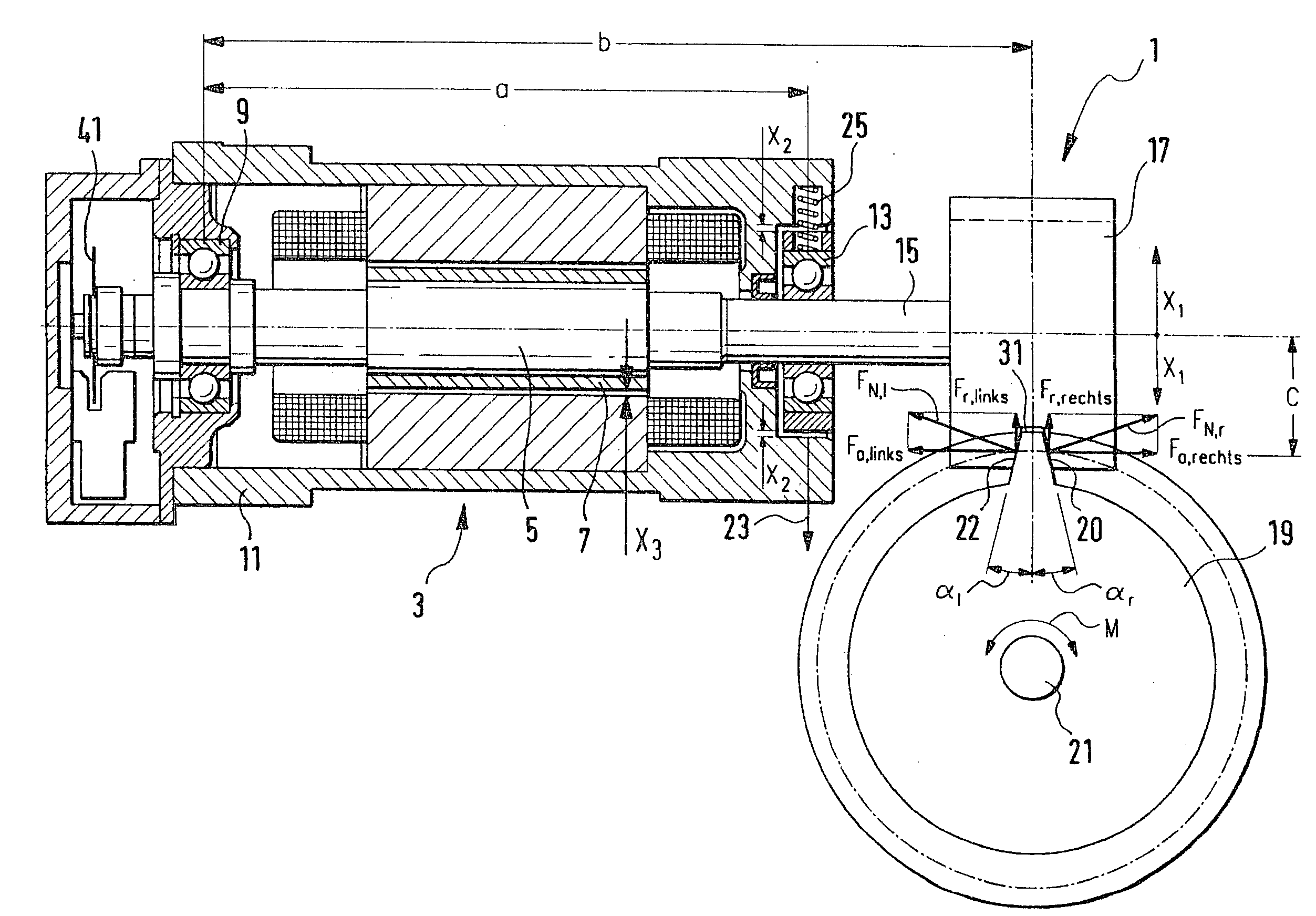
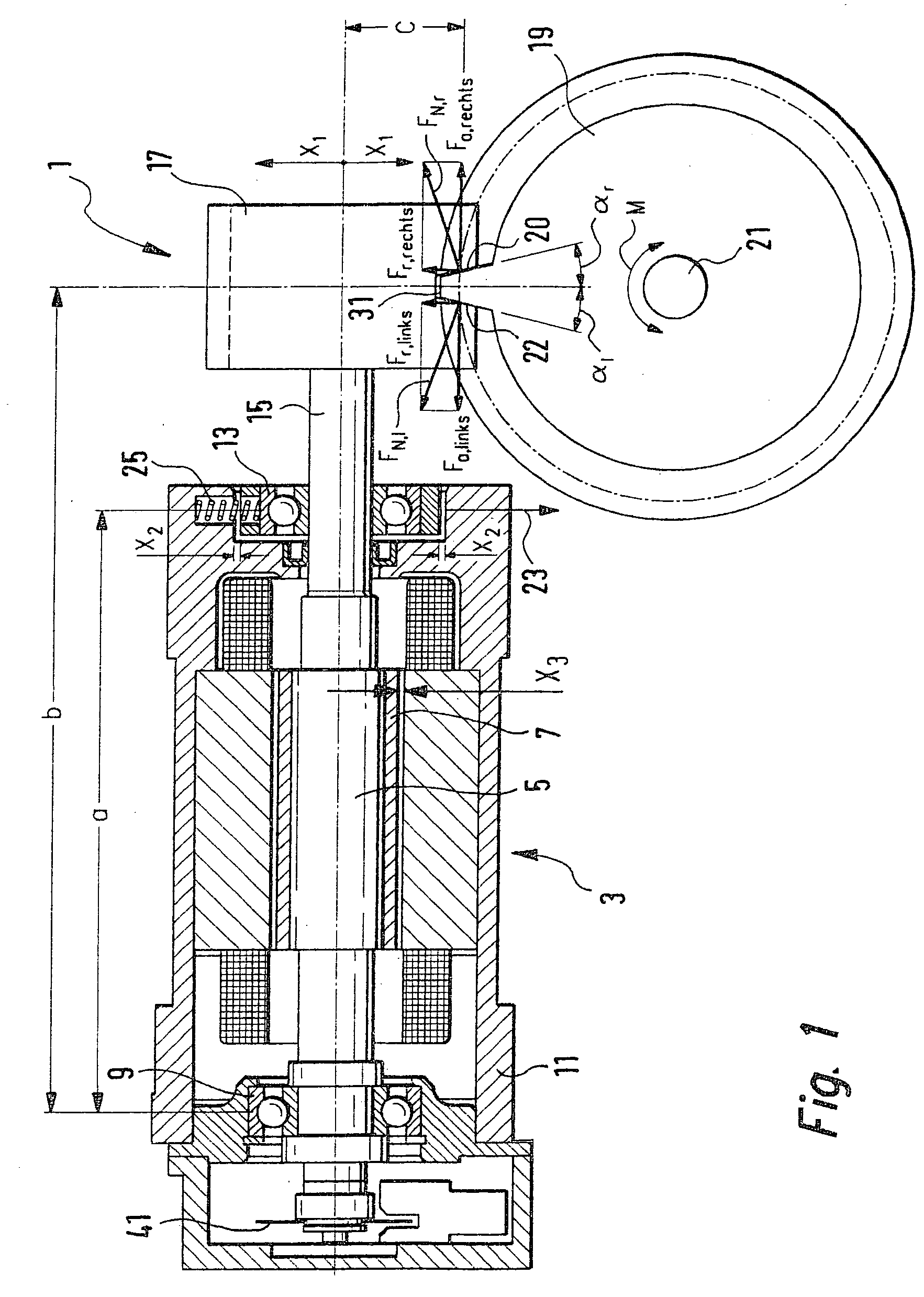
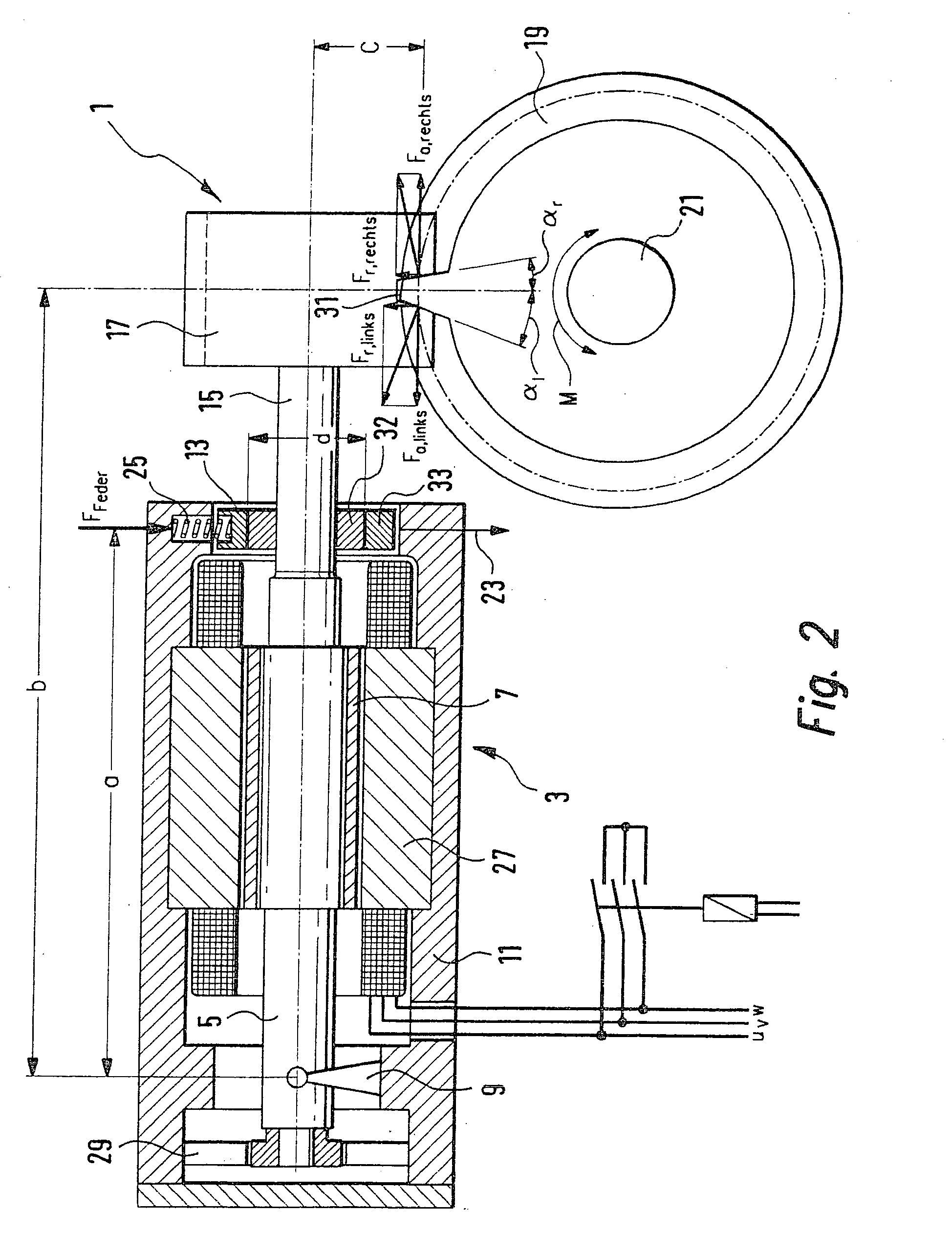
rque M Acts Counterclockwise (Mathematically Positive):
ΣM=Fa,r×c−Fspring×a+Fr,r×b=0
where: [0032] FN,r: normal force between the right tooth flank 20 of tooth 31 and the worm 17[0033] Fa,r: axial component of FN,r [0034] Fr,r: radial component of FN,r [0035] a, b, c: length of the effective lever arm
case 2
rque M Acts Clockwise (Mathematically Negative):
ΣM=−Fa,l×c−Fspring×a+Fr,r×b=0
where: [0036] FN,l: normal force between the left tooth flank 22 of tooth 31 and the worm 17[0037] Fa,l: axial component of FN,l [0038] Fr,l: radial component of FN,l [0039] a, b, c: length of the effective lever arm
[0040] Due to the different signs of Fa,r and Fa,l, the self-inhibition of the worm gear 1 illustrated in FIG. 1 is dependent on the direction of rotation. This effect is undesirable, for example, when the worm gear 1 is used in a servo unit of an electric servo steering system, in a rack-and-pinion steering gear, in a steering actuator, in a speed modulation gear and / or as the steering actuator of a steer-by-wire steering system.
[0041] Symmetrical behavior can be achieved for worm gear 1 if the pressure angle αr of right tooth flank 20 and the pressure angle αl of left tooth flank 22 of tooth 31 are selected as different.
[0042] An exemplary embodiment of a worm gear 1 according to the inve...
PUM
 Abstract
Description
Claims
Application Information