

Metallic implant and process for treating a metallic implant
a technology of metallic implants and metal coatings, applied in the field of biocompatibility of metallic bone implants, can solve the problems of ultimate failure of implants, brittle ceramic coatings, and functional parts of implants that cannot be attached, and achieve the effect of improving biocompatibility
- Summary
- Abstract
- Description
- Claims
- Application Information
AI Technical Summary
Benefits of technology
Problems solved by technology
Method used
Image

Examples
example 1
[0051] Seven surgical implants, commercially pure (c.p.) titanium, 5 mm in length and generally conical in shape having a diameter at one end of 3 mm and at the other end 2 mm, were prepared by machining using a “Maximat super 11”™ turning lathe. Therefore the area of the conical sides of the implant, i.e. the part of the implant to be located in the bone, is 39 mm2.
[0052] Each implant was cleaned according to a well-known cleaning procedure involving the following steps: [0053] 1. Treatment with trichloroethylene with ultrasonic treatment, for 15 minutes. [0054] 2. Rinsing in absoute ethanol, for 10 seconds. [0055] 3. Three successive treatments with ethanol with ultrasonic treatment, each for 10 minutes.
[0056] Each cleaned implant was sterile packaged in a Mediplast™ sterile envelope, and autoclaved in a Citomat 162™ (LIC Company) autoclave, at 120 C for 30 minutes.
[0057] A HF bath was prepared simply by diluting concentrated HF with distilled water, to give 0.2% solution. The ...
example 2
[0067] Reference implants were made of titanium grade 3, and were made by turning at an average speed of about 7 meters per minute. No cutting fluid was used. The cutting tool was made of high speed steel.
[0068] The reference implant surface was cleaned by a standard cleaning procedure involving the following steps: [0069] 1. Treatment with trichloroethylene with ultrasonic treatment for 15 minutes. [0070] 2. Rinsing in absolute ethanol for 10 seconds. [0071] 3. Three successive treatments with ethanol with ultrasonic treatment, each for 10 minutes. Each cleaned implant should then be sterile package in a Mediplast™ sterile envelope and autoclaved in a Citomat 62™ (LIC Company) autoclave at 120° C. for 30 minutes.
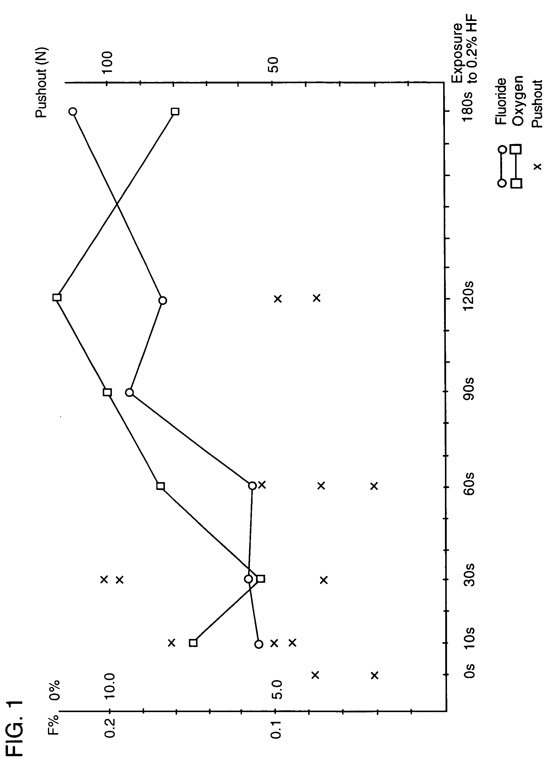
[0072] The result of an experiment in which the force necessary for removing (pushing out) substantially conical, unthreaded implants treated in 0.2% aqueous solution of hydrofluoric acid at room temperature for different time periods is illustrated in the diagram in FIG....
example 3
[0081] Another way of describing the effect of treatment is by means of the induction of Calcium Phosphate Precipitation. This is an in vitro test described in “Damen, Ten Cate, Ellingsen, Induction of Calcium Precipitation by titanium Dioxide, Journal of Dental Research, October 1991”. In this method an implant is immersed in a saturated solution of calcium phosphate. Depending on the surface, precipitation of calcium onto the implant occurs. The concentration of Ca++ is monitored and the time delay (the induction time) until precipitation occurs is measured. The rationale behind this test is the assumption that there is a correlation between the affinity of the implant surface towards the calcium ions and the biocompatibility of the implant surface in bone tissue. The results of the test are illustrated in the appended diagrams, FIGS. 7-10. The concentration of Ca++ is given on the Y-axis (2.00e-1 means 2.00×10⁻¹ etc). The test time is given on the X-axis in minutes.
[0082] The im...
PUM
| Property | Measurement | Unit |
|---|---|---|
| Fraction | aaaaa | aaaaa |
| Fraction | aaaaa | aaaaa |
| Fraction | aaaaa | aaaaa |
Abstract
Description
Claims
Application Information