Configuration and method for bidirectional transmission of signals in a motor vehicle

a technology for motor vehicles and signals, applied in the direction of near-field systems using receivers, near-field systems for reading/writing/interrogation/identification, transportation and packaging, etc., can solve the problem of high accident risk, and achieve the effect of keeping energy signals relatively small

Inactive Publication Date: 2005-07-28
SIEMENS AG
View PDF25 Cites 97 Cited by
  • Summary
  • Abstract
  • Description
  • Claims
  • Application Information

AI Technical Summary

Benefits of technology

[0015] The speed information would not have to reach each individual transceiver. A central control unit can also receive the speed information and instruct the transceivers connected to it to transmit a request signal as a function of speed. The central control unit also ensures that the transceivers of the vehicle are not activated simultaneously to send out the request signal.
[0016] Thus such a configuration can be used for a tire pressure measuring system with a passive transponder, in which an energy transmitter as well as a data receiver are each assigned to a wheel and are disposed in its vicinity on the vehicle side. A data transmitter and also an energy receiver are each disposed in a tire of the vehicle. This configuration with the two units close to one another allows the energy signals to be kept relatively small. If the triggering of the energy signals (i.e. the timing of the energy signals) is also undertaken as a function of the speed, these signals interfere with each other less frequently with functionally identical systems of other vehicles and vice versa.
[0017] The data transmitter is advantageously connected to a tire pressure sensor, a temperature sensor, a tire wear sensor or a load sensor. This allows the current tire parameters to be requested frequently enough and on deviation from reference values a visual or audible indication can be triggered for the driver.

Problems solved by technology

This is because it is precisely at higher speed that there is a higher risk of an accident if tire pressure is not sufficient.

Method used


Image

  • Configuration and method for bidirectional transmission of signals in a motor vehicle
  • Configuration and method for bidirectional transmission of signals in a motor vehicle
  • Configuration and method for bidirectional transmission of signals in a motor vehicle

Examples


Embodiment Construction

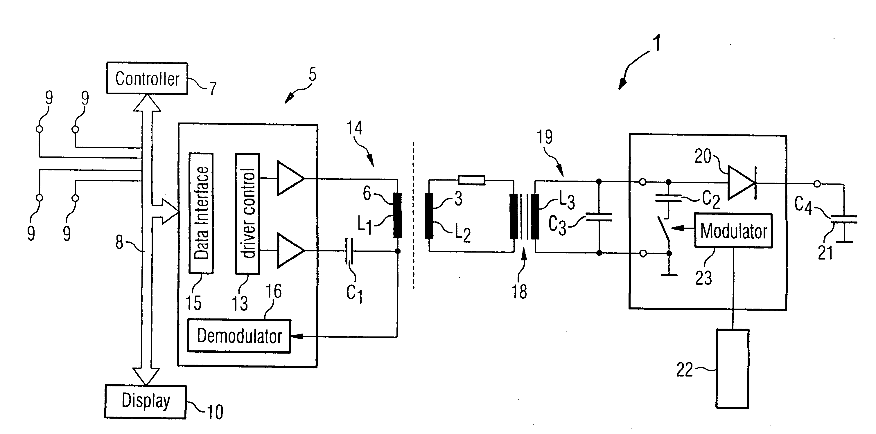
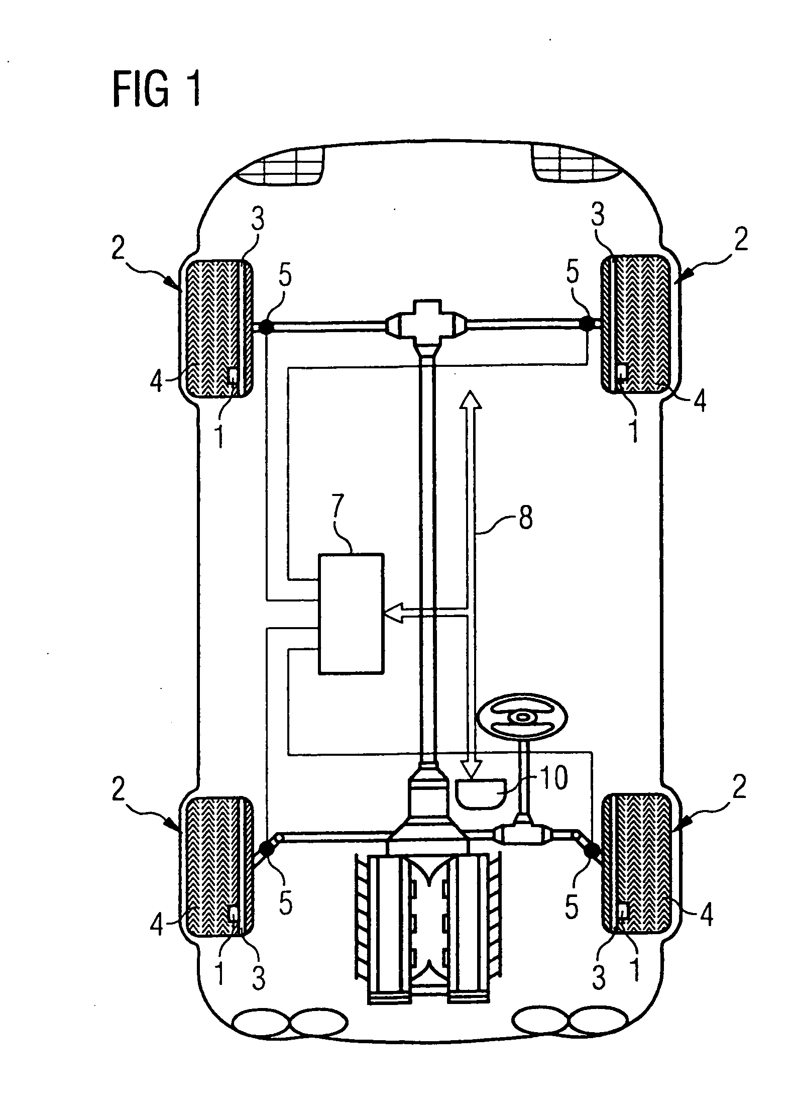
[0032] Referring now to the figures of the drawing in detail and first, particularly, to FIG. 1 thereof, there is shown a configuration and a method for bidirectional transmission of signals between two transceiver units disposed remotely from one another in the motor vehicle and is explained below using a tire pressure measuring system as an exemplary embodiment. In this case a transceiver is used to transmit energy to a passive transponder, which triggers the return of tire data from the transponder to the transceiver.

[0033] A “transponder” here is taken to mean an electrical device which can both receive and transmit signals. Various information data is modulated onto the transmitted signal in this case. Such information can be measured values or also other physical parameters such as tire pressure, temperature, revolutions, accelerations, tire wear, loading, etc. Fixed information can also be modulated onto the signal, such as for example a tire identification code. With transp...


PUM


Abstract

A method for operating a tire pressure measuring system uses a transceiver. When triggered, the transceiver transmits an energy signal to a transponder in a tire that then responds with a data signal. So that the energy signals do not interfere with other transceivers on receipt of the data signals, the method makes provision for the repetition rate with which the energy signals are triggered to be a function of the speed of the vehicle. Transmission is more frequent at higher speed than at lower speed.

Description

BACKGROUND OF THE INVENTION [0001] Field of the Invention [0002] The invention relates to a configuration and a method for bidirectional transmission of signals in a motor vehicle, with receipt of a request signal triggering a response signal with data information. [0003] Such a configuration is known for example from U.S. Pat. No. 6,581,449 B1. The patent describes a warning system, in which the tire pressure in each tire is monitored and an indication is given if the pressure is too low. [0004] Such a system features a transmitter-receiver pair (referred to hereafter as a transceiver) that is assigned to a wheel of the vehicle in each case. A receiver-transmitter pair (referred to below as a transponder) is disposed in each tire. The transmitter of the transceiver first sends an energy signal on activation. The signal causes the transponder to return current tire parameters of the relevant tire to the vehicle. [0005] In this case the transceiver transmits over a relatively long pe...

Claims


Application Information

Patent Timeline
Patent Type & Authority Applications(United States)
IPC IPC(8): B60C23/04H04B5/02
CPCB60C23/0413B60C23/044B60C23/0461H04B5/02H04B5/0031H04B5/0037H04B5/0068B60C23/0464
Inventor KUCHLER, GREGORTURBAN, PETERWAGNER, DIETER
Owner SIEMENS AG
Why Eureka
Try Eureka