Multi-phase carrier signal generator and multi-phase carrier signal generation method

a multi-phase carrier and generator technology, applied in the direction of motor/generator/converter stopper, pulse technique, dynamo-electric converter control, etc., can solve the problems of configuration encountering difficulty in achieving high accuracy of carrier signal waveform and high accuracy of phase difference, and achieve the effect of enhancing phase difference accuracy

Inactive Publication Date: 2005-07-28
NIPPON YUSOKI
View PDF50 Cites 39 Cited by
  • Summary
  • Abstract
  • Description
  • Claims
  • Application Information

AI Technical Summary

Benefits of technology

[0029] In the embodiment of the present invention, counting of clock signals for respective phases is commenced simultaneously. As a result, a difference between the timings at which counting operations for respective phases are commenced is eliminated, thereby enhancing the accuracy of a phase difference between carrier signals of respective phases.
[0030] According to the present invention, triangular wave carrier signals having a phase ...

Problems solved by technology

Hence, the method of generating such a carrier signal becomes a problem.
Thus, the configuration encounters...

Method used


Image

  • Multi-phase carrier signal generator and multi-phase carrier signal generation method
  • Multi-phase carrier signal generator and multi-phase carrier signal generation method
  • Multi-phase carrier signal generator and multi-phase carrier signal generation method

Examples


first embodiment

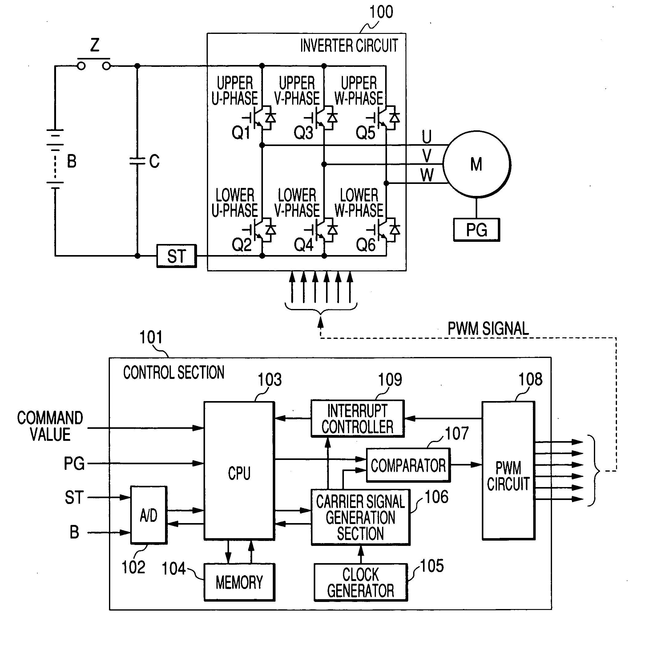
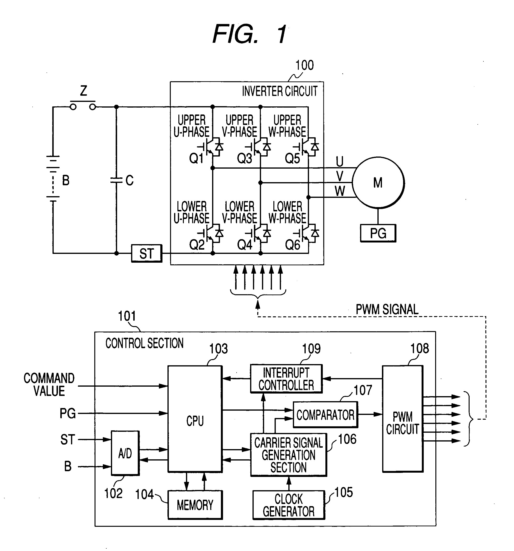
[0050]FIG. 1 shows an example of a controller of a three-phase AC motor equipped with a multi-phase carrier signal generator according to a first embodiment of the present invention. Reference symbol B denotes a battery, and power is supplied from this battery B to a motor M by way of a contactor Z and an inverter circuit 100. For instance, the motor M is a three-phase induction motor mounted on a forklift. The contactor Z is formed from a contact point of a magnetic contactor. Reference symbol C denotes a capacitor connected between power lines, and ST denotes a shunt for detecting an electric current flowing into the motor M. The shunt ST is formed from a resistor. Reference symbol PG denotes a pulse generator for detecting the revolutions per minute (RPM) of the motor M, and the pulse generator is formed from a known rotary encoder provided on a rotary shaft of the motor M.

[0051] The inverter circuit 100 is a circuit for driving the motor M by converting DC power of the battery ...

second embodiment

[0094]FIG. 13 shows an example of a controller of a three-phase AC motor equipped with a multi-phase carrier signal generator according to a second embodiment of the present invention. The controller shown in FIG. 13 is identical in basic configuration to the first embodiment of the present invention except the carrier signal generation section 116 and the comparator 117, and hence its explanation is omitted.

[0095] A control section 111 is equipped with the analog-to-digital converter 102, the CPU 103, the memory 104, the clock generator 105, a carrier signal generation section 116, a comparator 117, the PWM circuit 108, and the interrupt controller 109. The multi-phase carrier signal generator according to the second embodiment of the present invention is formed from the clock generator 105 and the carrier signal generation section 116.

[0096]FIG. 14 is a detailed block diagram of the carrier signal generation section 116 shown in FIG. 13. Reference numeral 110 designates a first ...


PUM


Abstract

A carrier signal generation section is provided for each of U, V, and W phases, and each of the carrier signal generation sections has an up-down counter for counting clock signals output from a clock generator. An initial value is set for each of the up-down counters. When the up-down counters are simultaneously started by method of a count start signal output from a CPU, the respective up-down counters start counting operations from the respective initial values, perform cumulative subtraction until the count value reaches an upper limit, and perform cumulative addition until the count value reaches a lower limit. As a result, triangular wave carrier signals Cu, Cv and Cw of respective phases having a predetermined phase difference can be readily generated with high accuracy.

Description

BACKGROUND OF THE INVENTION [0001] 1. Field of the Invention [0002] The present invention relates to a multi-phase carrier signal generator and a multi-phase carrier signal generation method, both being used for controlling PWM (Pulse Width Modulation) of a three-phase AC motor. [0003] 2. Description of the Related Art [0004]FIG. 6 shows a controller of a common three-phase AC motor operating under PWM control. In the drawing, reference symbol B denotes a battery, and power is supplied from this battery B to a motor M by way of a contactor Z and an inverter circuit 100. For instance, the motor M is a three-phase induction motor mounted on a forklift. The contactor Z is formed from a contact point of a magnetic contactor. In the drawing, reference symbol C denotes a capacitor connected between power lines, and ST denotes a shunt for detecting an electric current flowing into the motor M. The shunt ST is formed from a resistor. Reference symbol PG denotes a pulse generator for detecti...

Claims


Application Information

Patent Timeline
IPC IPC(8): H02M7/5387H02P27/08H04L27/28
CPCH02P27/08H02M7/53875
Inventor KATANAYA, IKUYA
Owner NIPPON YUSOKI
Why Eureka
Try Eureka